Waterproof structure of wet and dry dual-purpose dust collector motor

A wet and dry dual-purpose, waterproof structure technology, applied in the direction of electrical components, electromechanical devices, electric components, etc., can solve the problems of easy wear of the rotating shaft and the motor shell, increased frequency of motor self-protection, and reduced heat dissipation effect of the motor mechanism. To improve the self-radiation efficiency, reduce the probability of entering the motor mechanism, and reduce the production cost

Pending Publication Date: 2022-03-11
CINDERSON TECH (SUZHOU) CO LTD
View PDF4 Cites 0 Cited by
  • Summary
  • Abstract
  • Description
  • Claims
  • Application Information

AI Technical Summary

Problems solved by technology

[0003] When the motor drives the rotating shaft to rotate at high speed, wear is prone to occur between the rotating shaft and the motor housing, resulting in a gap between the rotating shaft and the motor housing. In order to reduce the moisture generated by the airflow from the fan into the motor housing through the gap and further damage the motor mechanism Adverse effects caused by operation, the conv

Method used


Image

  • Waterproof structure of wet and dry dual-purpose dust collector motor
  • Waterproof structure of wet and dry dual-purpose dust collector motor
  • Waterproof structure of wet and dry dual-purpose dust collector motor

Examples


Example Embodiment

[0038] Embodiment one:

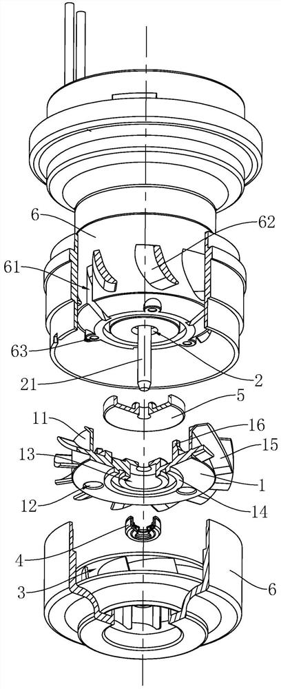
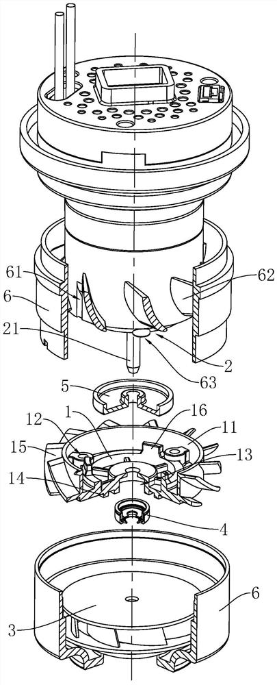
[0039] The embodiment of the present application discloses a waterproof structure for a wet and dry vacuum cleaner motor. refer to figure 1 , a waterproof structure for a wet and dry vacuum cleaner motor, including a waterproof plate 1, three connecting holes 12 are opened on the waterproof plate 1 along the circumferential direction, and the three connecting holes 12 and the three threaded holes provided on the motor housing 6 63 corresponds to facilitate the connection of the waterproof pan 1 to the motor housing 6 through bolts. The rotating shaft 21 connected to the motor mechanism 2 in the motor passes through the axis of the waterproof disk 1, and the rotating shaft 21 is not in contact with the waterproof disk 1 to prevent abrasion between the rotating shaft 21 and the waterproof disk 1.

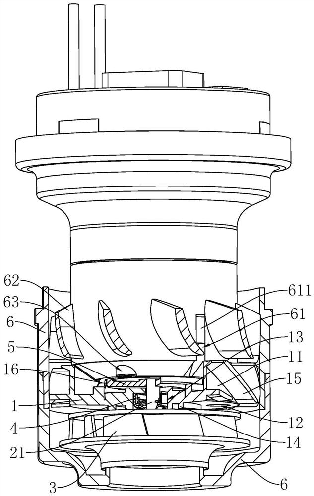
[0040] refer to figure 2 and image 3, the side of the waterproof disk 1 is connected with a windshield wall 11 along the circumferential direction. When...

Example Embodiment

[0053] Embodiment two:

[0054] The difference between the embodiment of the present application and the first embodiment lies in that the structure on the waterproof pan 1 for positioning with the motor casing 6 is different.

[0055] refer to Figure 4 and Figure 5 , the top wall of the waterproof disk 1 is connected with three wedge-shaped positioning strips 17, and the three positioning strips 17 are evenly distributed on the inner wall of the windshield wall 11, and are connected with the three pressure relief grooves 61 provided on the motor housing 6 one by one. Corresponding fitting fit, so that when the three positioning strips 17 are fitted with each pressure relief groove 61 on the motor housing 6 respectively, the three connection holes 12 on the waterproof disk 1 are respectively connected to the three connection holes 12 on the motor housing 6. The threaded holes 63 correspond to each other, and ensure the stability when the waterproof pan 1 and the motor hous...


PUM


Abstract

The invention relates to the field of motor waterproof technologies, in particular to a waterproof structure of a wet and dry dual-purpose dust collector motor, and solves the problems that the heat dissipation effect becomes poor and the operation of a dust collector is affected after a motor mechanism is subjected to waterproof and antirust spraying. The edge of the waterproof disc is provided with a wind blocking wall tightly attached to the motor shell, the waterproof disc is provided with a plurality of connecting holes used for being in bolt connection with the motor shell, one side face of the waterproof disc is provided with an embedded groove, an oil seal is arranged in the embedded groove, and the oil seal is arranged outside the rotating shaft in a sleeving mode. The effect of improving the waterproof performance between the motor shell and the rotating shaft of the dust collector is achieved.

Description

technical field [0001] The present application relates to the field of motor waterproof technology, in particular to a waterproof structure of a wet and dry vacuum cleaner motor. Background technique [0002] The vacuum cleaner motor is the heart of the vacuum cleaner. The vacuum cleaner motor is mainly composed of the motor part and the fan part. Since the vacuum cleaner motor has high requirements on the speed, generally 80000-120000 rpm, it mainly uses a DC brushless motor to connect the fan to the motor. On the rotating shaft, a filter device is arranged outside the suction port of the fan. When the motor drives the fan to rotate, the fan sucks the dirt aligned with the suction port into the filter device and collects it. [0003] When the motor drives the rotating shaft to rotate at a high speed, wear is prone to occur between the rotating shaft and the motor housing, resulting in a gap between the rotating shaft and the motor housing. In order to reduce the moisture ca...

Claims


Application Information

Patent Timeline
IPC IPC(8): H02K5/124H02K5/10H02K7/14H02K5/04
CPCH02K5/124H02K5/10H02K7/14H02K5/04
Inventor 朱云舫
Owner CINDERSON TECH (SUZHOU) CO LTD
Why Eureka
Try Eureka