

Cleaning tool for automobile seat lead screw
A technology for car seats and screw rods, applied in the direction of cleaning methods using liquids, cleaning methods and utensils, chemical instruments and methods, etc., can solve problems such as time-consuming and laborious, high production costs, damage to car seat screw rods, etc., to achieve Ease of use and the effect of reducing the defect rate
- Summary
- Abstract
- Description
- Claims
- Application Information
AI Technical Summary
Problems solved by technology
Method used
Image

Examples
Embodiment 1
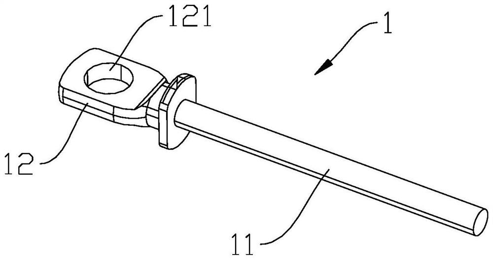
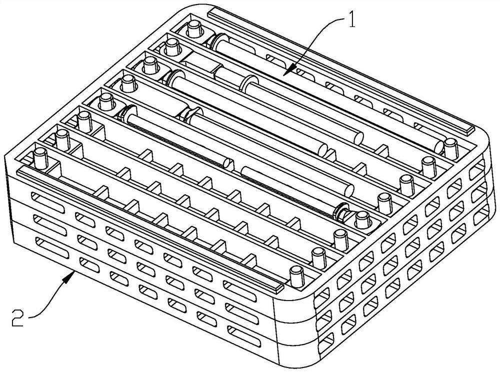
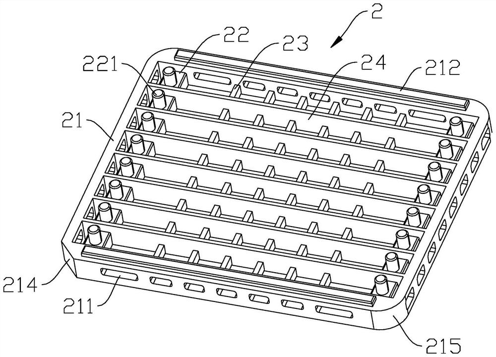
[0028] Embodiment one: if Figure 2-5 As shown, a cleaning tool for screw rods of automobile seats includes at least two trays 2 stacked from bottom to top. 23 and a plurality of partitions 24, the positioning bar 22 and the transverse rib 23 extend along the front-to-back direction, the front and rear ends of the positioning bar 22 and the front and rear ends of the transverse rib 23 are fixedly connected with the inner sidewall of the square frame 21 respectively, and all transverse ribs 23 are located at two Between the positioning bars 22; the dividing plate 24 extends along the left and right direction, the left and right ends of the dividing plate 24 are fixedly connected with the inner sidewall of the square frame 21, the dividing plate 24 and the positioning bar 22, the transverse rib 23 intersect to form a mesh, and the dividing plate 24 will The inside of the square frame 21 is divided into a plurality of placing grooves 25, and the upper end surface of the positioni...
Embodiment 2
[0030] Embodiment two: all the other parts are identical with embodiment one, and its difference is that the four sides of square frame 21 are respectively provided with a plurality of through holes 211, and the through holes 211 on the front and rear sides of square frame 21 and transverse rib 23, positioning The strips 22 are staggered, and the through holes 211 on the left and right sides of the square frame 21 are staggered with the partition plate 24 .
[0031] In this embodiment, there are gaps 26 between the positioning bar 22 on the left side and the left side inner wall of the square frame 21, and between the positioning bar 22 on the right side and the right side inner wall of the square frame 21. The length of the gap 26 is The through hole 211 located on the left and right sides of the square frame 21 communicates with the gap 26 .
Embodiment 3
[0032] Embodiment 3: The remaining parts are the same as Embodiment 1, the difference is that the diameter of the positioning column is 8 mm to 12 mm, and the distance between the center of the positioning column and the left and right side inner walls of the square frame is not less than 6.5 mm. The distance between the outer surface of the positioning column on the left and the left inner wall of the square frame is 9mm, and the distance between the outer surface of the positioning column on the right and the right inner wall of the square frame is 9mm, which has good versatility.
[0033] The distance between the positioning bar 22 and the transverse rib 23 is not less than 30 mm.
[0034]In this embodiment, the upper end surface of the partition plate 24 is flush with the upper end surface of the square frame 21 , and the lower end surface of the partition plate 24 is flush with the lower end surface of the square frame 21 .
[0035] In this embodiment, the front and rear ...
PUM
| Property | Measurement | Unit |
|---|---|---|
| Length | aaaaa | aaaaa |
| Diameter | aaaaa | aaaaa |
Abstract
Description
Claims
Application Information