Internal chamfering equipment of drainage pipe for water conservancy project

A technology of water conservancy projects and drainage pipes, which is applied to metal processing equipment, drainage structures, sewer pipe systems, etc., to achieve the effects of avoiding waste of water resources, improving work efficiency, and recycling water resources

Pending Publication Date: 2022-03-15
顾金涛
View PDF14 Cites 0 Cited by
  • Summary
  • Abstract
  • Description
  • Claims
  • Application Information

AI Technical Summary

Problems solved by technology

[0004] In order to overcome the traditional drainpipe chamfering method, the motor is usually installed with a chamfering tool, and then the inside of the drainpipe is chamfered by manually holding the motor, which has the disadvantage of manual uncertainty. The technical problem of the present invention is : To provide a water conservancy engineering drainage pipe internal chamfering device which has cooling function and can recycle water resources

Method used


Image

  • Internal chamfering equipment of drainage pipe for water conservancy project
  • Internal chamfering equipment of drainage pipe for water conservancy project
  • Internal chamfering equipment of drainage pipe for water conservancy project

Examples


Embodiment 1

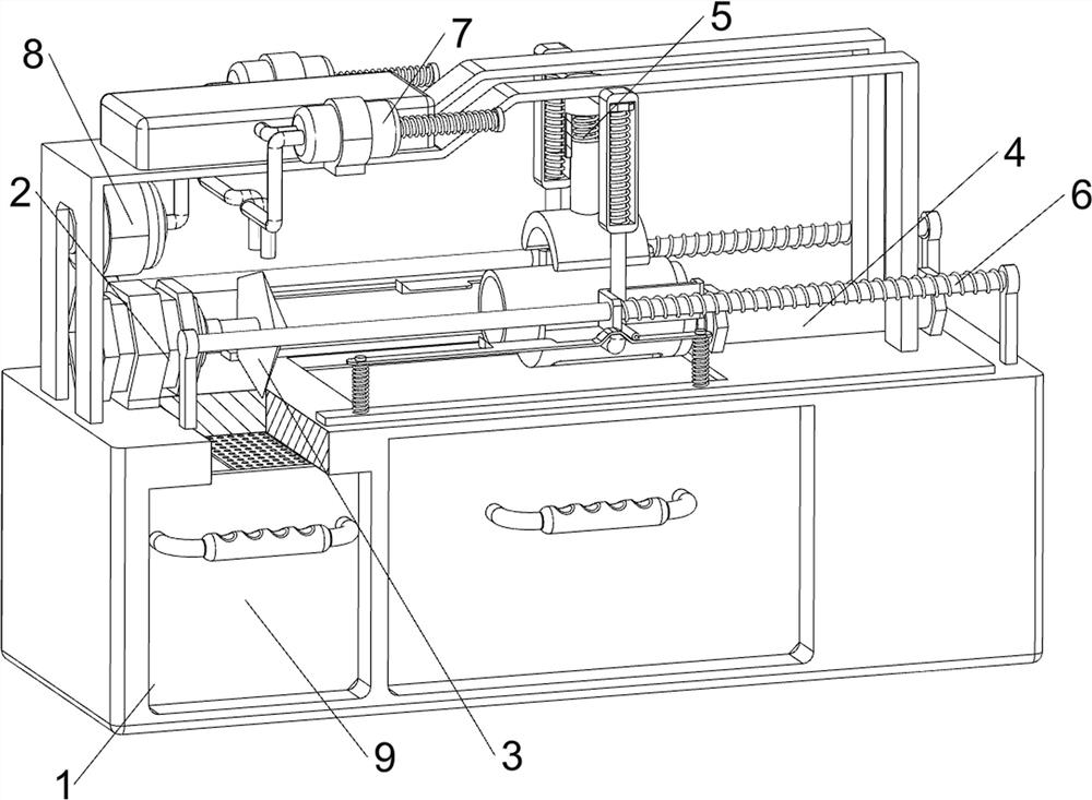
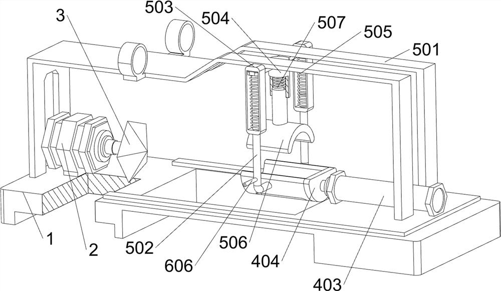
[0026] A kind of internal chamfering equipment for drainage pipes used in water conservancy projects, such as Figure 1-Figure 3 As shown, it includes a box body 1, a motor 2, a chamfering knife 3, a placement component 4 and a pressing component 5. A motor 2 is provided in the middle of the left side of the box body 1, and a chamfering knife 3 is provided on the output shaft of the motor 2. A placement component 4 is provided on the box body 1 , and a compression component 5 is provided on the inner upper side of the box body 1 , and the compression component 5 is connected with the placement component 4 .

[0027] The placement assembly 4 includes a box door 401, a control panel 402, a cylinder 403 and a placement slot 404. The box door 401 is slidingly provided in the middle of the front side of the box body 1, and a control panel 402 is provided on the upper right side of the front side of the box body 1. The box body 1 The inner middle right side is provided with a cylind...

Embodiment 2

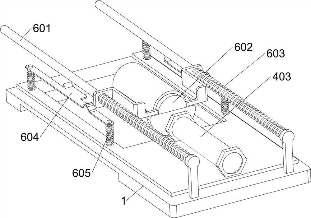
[0031] On the basis of Example 1, such as Figure 4-Figure 7As shown, a discharge assembly 6 is also included. The discharge assembly 6 includes a guide rod 601, a discharge plate 602, a third spring 603, a wedge plate 604, a fourth spring 605 and a connecting rod 606. The symmetrical sliding type is provided with a wedge-shaped plate 604, and the left side of the wedge-shaped plate 604 is provided with an oblique angle. The inner middle of the box 1 is provided with a guide rod 601 symmetrically, and the sliding type is provided with a discharge plate 602 in the middle of the guide rod 601. A support rod 502 cooperates with the unloading plate 602, and the unloading plate 602 cooperates with the bevel on the wedge plate 604, and the third spring 603 is arranged between the unloading plate 602 and the guide rod 601, and the third spring 603 is set on the guide rod On 601, fourth springs 605 are symmetrically arranged between the wedge plate 604 and the box body 1, and connecti...


PUM


Abstract

The invention relates to chamfering equipment, in particular to internal chamfering equipment of a drainage pipe for a water conservancy project. According to the technical aims, the chamfering equipment for the interior of the drainage pipe for the water conservancy project has a cooling function and can recycle water resources. According to the technical scheme, the chamfering equipment for the interior of the drainage pipe for the water conservancy project comprises a box body and a motor, and the motor is arranged in the middle of one side of the interior of the box body; the chamfering cutter is arranged on an output shaft of the motor; the placing assembly is arranged on the box body; and the pressing assembly is arranged on the upper side in the box body, and the pressing assembly is connected with the placing assembly. According to the chamfering device, the sliding block and the pressing block move downwards, the first spring is compressed, meanwhile, the pressing block makes contact with the drainage pipe downwards, when the sliding block continues to move downwards, the second spring is compressed, at the moment, the pressing block tightly presses the drainage pipe, the pressing effect is achieved, and the drainage pipe can be stably chamfered.

Description

technical field [0001] The invention relates to a chamfering device, in particular to an internal chamfering device for a drainage pipe used in a water conservancy project. Background technique [0002] Drainage pipes are mainly responsible for the drainage of rainwater, sewage, farmland drainage and irrigation, etc. During the process of using the drainage pipe, it is necessary to connect the pipes of the drainage pipe according to the actual situation. In order to ensure the sealing of the connection during the connection process And firmness, before connecting, it is necessary to chamfer the inside of the drain pipe, and improve the sealing and firmness between the water pipes through the chamfering connection. At present, the traditional way of chamfering the drain pipe is usually to install the motor on the chamfering tool , and then use the manual hand-held motor to chamfer the inside of the drain pipe. There are uncertain factors in manual work, which makes the chamfe...

Claims


Application Information

Patent Timeline
IPC IPC(8): B23D79/00B23Q3/06B23Q7/00B23Q11/00E03F3/04E03F5/10E03F5/14E03F5/22
CPCB23D79/00B23Q3/06B23Q7/00B23Q11/00E03F5/22E03F5/14E03F5/10E03F3/04Y02P70/10
Inventor 顾金涛
Owner 顾金涛
Why Eureka
Try Eureka