Tire vulcanization equipment

A tire vulcanization and equipment technology, which is applied to tires, other household appliances, household appliances, etc., can solve the problems of motor damage and shortened service life of the motor, and achieve the effects of improving service life, avoiding shortened service life, and avoiding high temperature

Pending Publication Date: 2022-03-15
HIMILE MECHANICAL SCI & TECH (SHANDONG) CO LTD
View PDF4 Cites 2 Cited by
  • Summary
  • Abstract
  • Description
  • Claims
  • Application Information

AI Technical Summary

Problems solved by technology

[0004] However, the high temperature and high pressure environment will damage the motor and shorten the service life of the motor

Method used


Image

  • Tire vulcanization equipment
  • Tire vulcanization equipment
  • Tire vulcanization equipment

Examples


Embodiment 1

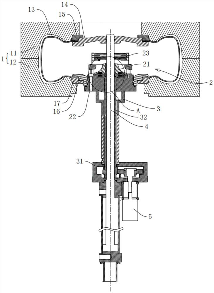
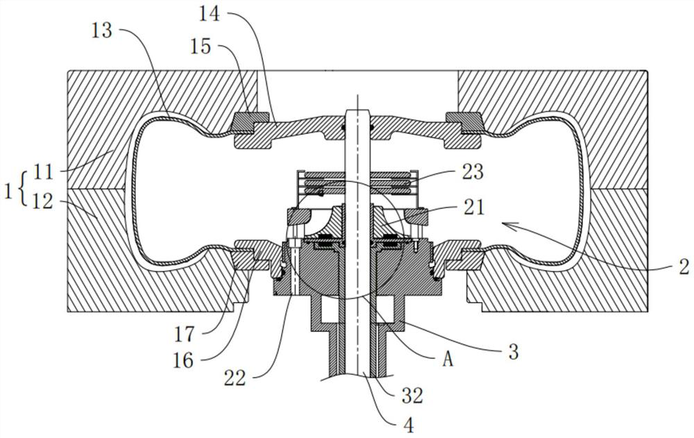
[0039] refer to figure 1 , the invention discloses a tire vulcanization equipment, comprising a mold assembly 1, a ring seat assembly 2 arranged inside the mold assembly 1, a cylinder assembly supporting the ring seat assembly 2, a driving member and a transmission assembly, and the ring seat assembly 2 is provided with a gas circulation fan 21, and the driving part drives the gas circulation fan 21 to rotate through the transmission assembly. The cylinder assembly includes the cylinder body 3 and the transmission box 31 arranged on the cylinder body 3.

[0040] refer to figure 1 and figure 2, The mold assembly 1 is a two-half mould, and can also be a two-half active mould, an upper-opening active mould, and a lower-opening active mould. Specifically, the mold assembly 1 includes an upper mold 11 and a lower mold 12. A vulcanization bladder 13 for molding the tire is also provided inside the mold assembly 1. The ring seat assembly 2 is located inside the vulcanization bladd...

Embodiment 2

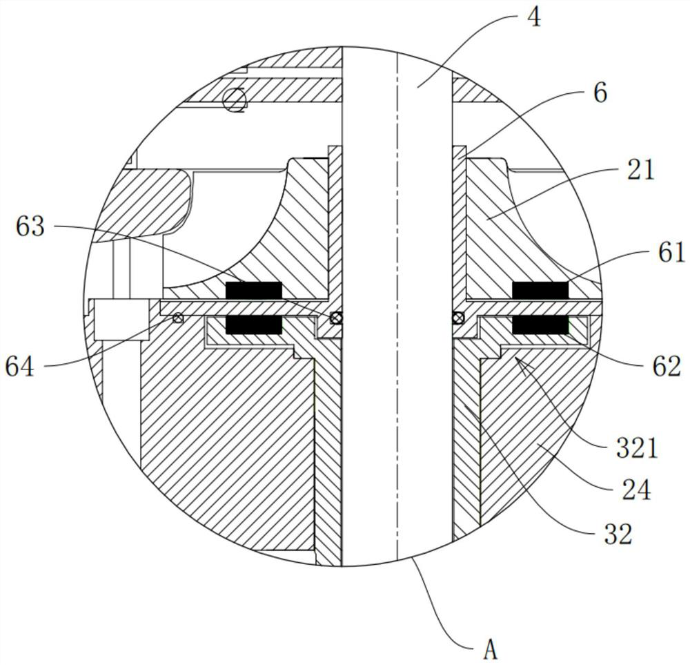
[0049] The difference between the second embodiment and the first embodiment lies in that the positions of the first magnetic body 61 and the second magnetic body 62 are different. refer to Figure 8 and Figure 9 , the transmission assembly includes a first transmission part and a second transmission part, the first transmission part is the first shaft body 311 , and the second transmission part is the second shaft body 51 . The tire vulcanization equipment also includes a transmission box 31, the transmission box 31 is arranged on the cylinder body 3, the transmission box 31 is penetrated by the rotating shaft 32, and the rotating shaft 32 is a hollow shaft, which is sleeved on the center rod 4 and is arranged in the cylinder body 3 , the top of the rotating shaft 32 is connected with the gas circulation fan 21 and drives it to rotate. The first shaft body 311 is arranged in the transmission box 31, and the first shaft body 311 and the rotating shaft 32 are gear meshed. Of...


PUM


Abstract

The invention relates to the field of tire vulcanizing machines and rubber vulcanizing devices, in particular to tire vulcanizing equipment which comprises a mold assembly, a ring seat assembly arranged in the mold assembly, a cylinder barrel assembly for supporting the ring seat assembly, a sealing cover for sealing gas in the mold assembly and a driving part. A rotating shaft for driving the gas circulating fan to rotate is arranged in the cylinder barrel assembly, the driving part drives the rotating shaft to rotate, and the sealing cover separates the driving part, so that high-temperature and high-pressure gas in the mold assembly cannot lose the driving part, and the service life of the driving part is prolonged.

Description

technical field [0001] The invention relates to the field of tire vulcanizing machines and rubber vulcanizing devices, in particular to tire vulcanizing equipment. Background technique [0002] At present, tire vulcanization is generally carried out by a combination of saturated steam and nitrogen. This vulcanization process is specifically to first pass saturated steam into the vulcanization bladder to provide the heat required for vulcanization. [0003] However, with the shortage of energy, rising steam prices, and the proposal of "dual carbon targets", electric heating vulcanizers have gradually been applied. The principle is to install heaters, fans or other spoiler components inside the vulcanizer capsule, and motors or other driving devices. Drive the fan or other turbulent components to rotate, so that a uniform high temperature and high pressure environment is generated inside the curing bladder. [0004] However, the high temperature and high pressure environment...

Claims


Application Information

Patent Timeline
Patent Type & Authority Applications(China)
IPC IPC(8): B29D30/06
CPCB29D30/0601B29D30/0662B29D2030/067
Inventor 孙日文高龙飞刘志兰赵阳方强宋锡涛
Owner HIMILE MECHANICAL SCI & TECH (SHANDONG) CO LTD
Why Eureka
Try Eureka