
Anti-clogging device capable of protecting spray nozzles along with flow of solution

An anti-clogging and nozzle technology, applied in the field of desulfurization and denitrification, can solve problems such as pollution, nozzle hole clogging, and shortened service life

Inactive Publication Date: 2019-10-18
杭州富阳锐明科技有限公司
View PDF6 Cites 3 Cited by
  • Summary
  • Abstract
  • Description
  • Claims
  • Application Information

AI Technical Summary

Problems solved by technology

[0002] The desulfurization of the desulfurization tower is mainly to avoid environmental pollution. Among them, the rotary spray desulfurization is widely used. However, in the existing technology, most of the desulfurization towers only consider the use of the rotary spray desulfurization method. In the process, the clogging structure and the like will occur, and it is not considered that the body of the rotating nozzle will dissipate the watery Ca(OH) 2 When turning into calcium hydroxide spray to remove sulfur, due to the fineness and easy-to-adhesive nature of water mist, a small amount of mist will adhere to the outer surface of the lower end of the nozzle body, and it will also interact with SO 2 reaction, i.e. SO 2 +Ca(OH) 2 →CaSO 4 +H 2 0, produce CaSO 4 The fixed body is attached to the lower end of the nozzle body, and it will gradually block the nozzle hole under the spray in the long run, resulting in the nozzle hole being eventually blocked, and the nozzle body can no longer be used for spraying, and the service life is shortened

Method used


Image

  • Anti-clogging device capable of protecting spray nozzles along with flow of solution
  • Anti-clogging device capable of protecting spray nozzles along with flow of solution
  • Anti-clogging device capable of protecting spray nozzles along with flow of solution

Examples


Embodiment Construction

[0023] The following will clearly and completely describe the technical solutions in the embodiments of the present invention with reference to the accompanying drawings in the embodiments of the present invention. Obviously, the described embodiments are only some, not all, embodiments of the present invention. Based on the embodiments of the present invention, all other embodiments obtained by persons of ordinary skill in the art without making creative efforts belong to the protection scope of the present invention.

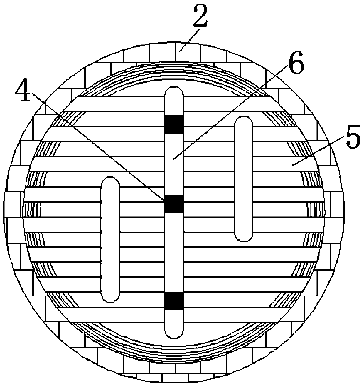
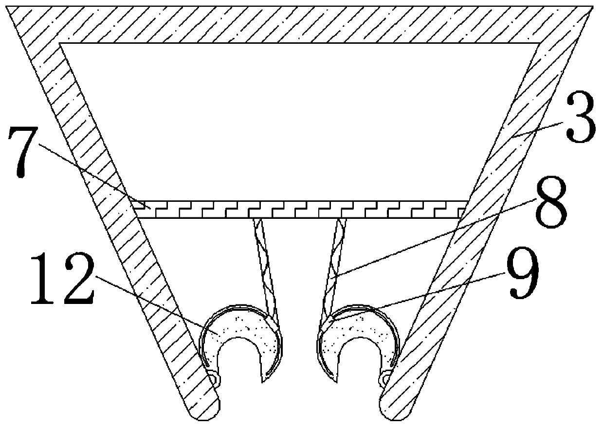
[0024] see figure 1 , an anti-clogging device that can follow the flow of the solution to protect the spray nozzle, including a spray pipe 1, a groove 201 is fixedly installed on the lower surface of the spray pipe 1, and the inside of the spray pipe 1 and the groove 201 are fixed , a fixed disk 2 is installed.

[0025] see figure 2 : The vibrating strip 5 is fixedly installed inside the fixed plate 2, and the descaling strip 6 is fixedly installed on the s...


PUM


Abstract

The invention provides an anti-clogging device capable of protecting spray nozzles along with flow of a solution. The device comprises a spray pipe, and grooves are fixedly installed at the lower surface of the spray pipe; and fixing discs are installed between the interior of the spray pipe and the grooves, vibrating strips are fixedly installed in each fixing disc, descaling strips are fixedly installed at the side surface of the vibrating strips, mixing strips are fixedly installed on two sides of each descaling strip, and one movable ball is fixedly installed at the right end of each mixing strip located at the right side. According to the device provided by the invention, the mixing strips and the movable balls cooperate for use, so that spray nozzle bodies can be effectively prevented from being blocked, and a calcium hydroxide solution which is not completely dissolved is prevented from forming a precipitate to cause the spray nozzle bodies to be blocked; and the mixing strips located on the left side of the fixing discs continues to oscillate under continuous introduction of a calcium hydroxide solution to continue to uniformly mixing the solution.

Description

technical field [0001] The invention relates to the technical field of desulfurization and denitrification, in particular to an anti-clogging device that can follow the flow of a solution to protect a spray nozzle. Background technique [0002] The desulfurization of the desulfurization tower is mainly to avoid environmental pollution. Among them, the rotary spray desulfurization is widely used. However, in the existing technology, most of the desulfurization towers only consider the use of the rotary spray desulfurization method. In the process, the clogging structure and the like will occur, and it is not considered that the body of the rotating nozzle will dissipate the watery Ca(OH) 2 When turning into calcium hydroxide spray to remove sulfur, due to the fineness and easy-to-adhesive nature of water mist, a small amount of mist will adhere to the outer surface of the lower end of the nozzle body, and it will also interact with SO 2 reaction, i.e. SO 2 +Ca(OH) 2 →CaSO ...

Claims


Application Information

Patent Timeline
Patent Type & Authority Applications(China)
IPC IPC(8): B01D53/78B01D53/60B05B15/50
CPCB01D53/60B01D53/78B01D2251/404B01D2251/604B05B15/50
Inventor 徐梦姣熊烽刘爱莲
Owner 杭州富阳锐明科技有限公司
Learn More