

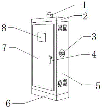
Power distribution automation monitor terminal
A distribution automation and monitoring terminal technology, which is applied in substation/power distribution device housing, electrical components, circuit devices, etc., can solve problems such as short circuit and fire, difficult to determine, and danger, so as to avoid shortened service life, facilitate modification and Setting and increasing the effect of operational safety
- Summary
- Abstract
- Description
- Claims
- Application Information
AI Technical Summary
Problems solved by technology
Method used
Image

Examples
specific Embodiment approach
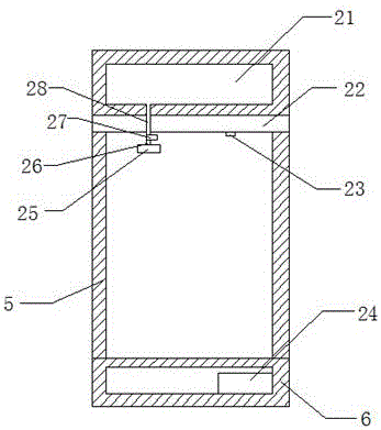
[0028]Specific implementation method: first, the installer connects the present invention to an external power supply, and the external power supply transmits electric energy to the storage battery 24, which stores electric energy inside. Above, the resistance value of the photoresistor 23 decreases rapidly until the circuit between the storage battery 24 and the solenoid valve 27 is connected, the electric energy in the storage battery 24 is transmitted to the solenoid valve 27 through the wire, and the solenoid valve 27 converts the electric energy into mechanical energy, and opens the conduit The gate valve between one 28 and conduit two 26, the foam in the foam chamber 21 flows through conduit one 28 and conduit two 26 to the nozzle 25, and the nozzle 25 sprays the foam inside the present invention. This design solves the problem of power distribution monitoring terminal due to The problem that the fire caused by the short circuit cannot be extinguished in a short time avoi...
PUM
 Abstract
Description
Claims
Application Information