Coplanar rod type truss node

A rod-type and truss technology, applied in the field of coplanar rod-type truss joints, can solve problems such as difficulty, delay in construction period, and inability to establish connections in truss structures, so as to improve construction efficiency and reduce construction difficulty

Pending Publication Date: 2022-03-15
BEIJING URBAN CONSTR GROUP
View PDF0 Cites 0 Cited by
  • Summary
  • Abstract
  • Description
  • Claims
  • Application Information

AI Technical Summary

Problems solved by technology

The web system needs to have various forms of structure according to the design requirements; the joint design of the truss structure is closely related to the connection method and the web system; the truss joint structure in the prior art only has two types: plate joints and spherical joints; The positions of the nodes and the spherical nodes are all fixed positions, and the orientation of the rods connected to the nodes is also fixed; during the construction process, once the truss rods have a slight deviation, the truss structure cannot be connected; it is difficult to repair the truss structure. It is very large and greatly delays the construction period

Method used


Image

  • Coplanar rod type truss node
  • Coplanar rod type truss node
  • Coplanar rod type truss node

Examples


Embodiment 1

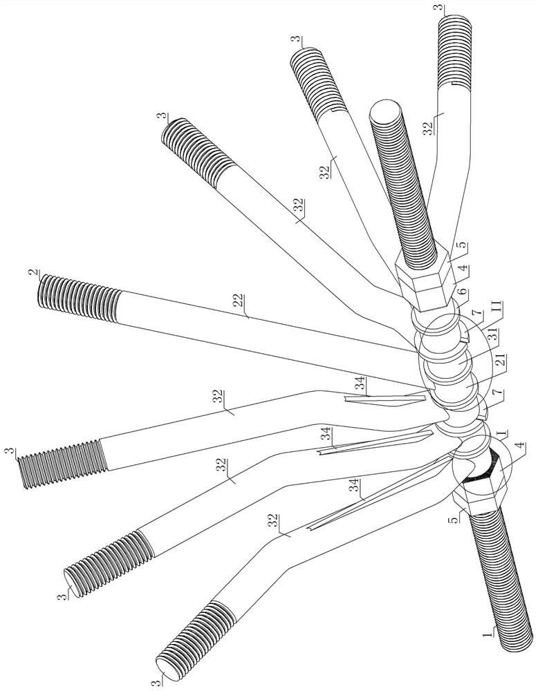
[0030] Embodiment one: see Figure 1-10 , a coplanar bar truss joint, including an adjusting screw, a middle member, two side members and a fixing nut;

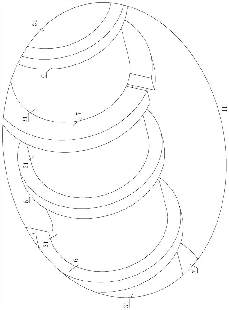
[0031] The adjusting screw is set horizontally, and both ends are connected with other parts of the truss structure; the adjusting screw is equipped with middle rods, rods on both sides, and fixing nuts on both sides; the adjusting screw is all coplanar rod trusses. Node bearing parts;

[0032] There is one middle rod, including the connected sleeve A and straight rod; the sleeve A slides and fits on the adjustment screw; one end of the straight rod is perpendicular to the sleeve A axis and is connected with the sleeve A, and the other end is connected with other parts of the truss structure connected; the middle rod is located in the middle of the coplanar rod truss node; the middle of the so-called coplanar rod truss node is not the center in the geometric sense, that is, the midpoint position of the adjustment screw, but ...

Embodiment 2

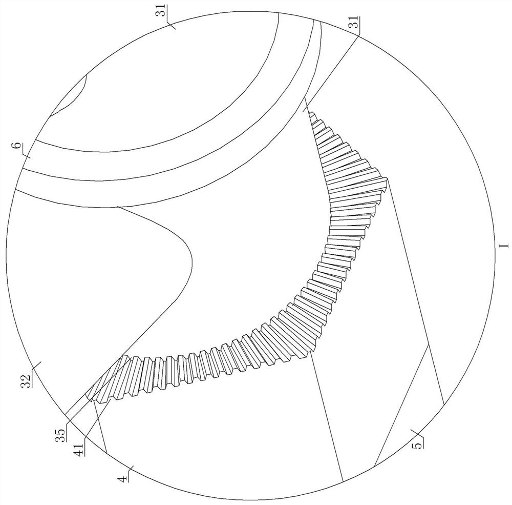
[0045] Embodiment two: refer to the appended Figure 1-5 , manual attached Figure 7-8 , manual attached Figure 10-12 , Embodiment 2 is basically the same as Embodiment 1, and the similarities will not be described in detail. The difference is that the thread profile of the external thread armor is smaller than the thread profile of the adjusting screw; the adjusting screw is a very important force-bearing part of the truss structure , The large tooth-shaped thread can ensure the mechanical strength of the adjusting screw; the external thread armor is only for the anti-loosening effect of the fixing nut, and does not require such a large mechanical strength.


PUM


Abstract

A coplanar rod type truss node comprises an adjusting lead screw, a middle rod piece, two side rod pieces and fixing nuts. The adjusting lead screw is perpendicular to the main stress face of the coplanar rod type truss joint. The adjusting lead screw is sleeved with a middle rod piece, two side rod pieces and a fixing nut from inside to outside. The middle rod piece comprises a sleeve A and a straight rod which are connected; the axis of the straight rod coincides with the main stress surface; the two side rod pieces comprise second sleeves and bent rods. One end of the bent rod is connected with the sleeve B, the middle part is bent and transited towards the middle rod piece, and the axis of the other end coincides with the main stress surface; the fixing nuts are in threaded connection with the adjusting lead screws on the two sides correspondingly, and the middle rod piece and the rod pieces on the two sides are clamped. The first sleeve and the second sleeve are arranged on the adjusting lead screw in a sleeving mode and can drive the middle rod piece and the rod pieces on the two sides to move in the axial direction of the adjusting lead screw and rotate around the axis of the adjusting lead screw so as to reach the proper position and orientation. The fixing nut A is fixed; therefore, more free orientation selection can be provided, and the deviation of the truss rod piece can be offset, so that the construction difficulty is reduced, and the construction efficiency is improved.

Description

technical field [0001] The invention relates to the technical field of steel structures, in particular to a coplanar bar type truss node. Background technique [0002] A truss structure refers to a planar or spatial structure composed of straight rods that generally has triangular units. Under load, the truss members mainly bear axial tension or pressure, so that the strength of the material can be fully utilized. When the span is large, it can save material, reduce self-weight and increase rigidity compared with solid web beams, so it is suitable for large spans. Load-bearing structures and high-rise structures, such as roof trusses, bridges, transmission line towers, satellite launch towers, hydraulic gates, crane frames, etc. Compared with the steel beam of the solid web type, the steel truss is characterized by replacing the flange with the chord and the web with the web, and connecting the web at each node through the gusset plate (or other parts) with welds or other c...

Claims


Application Information

Patent Timeline
Patent Type & Authority Applications(China)
IPC IPC(8): E04B1/19
CPCE04B1/1903E04B2001/1918E04B2001/196
Inventor 李峰杨雪生尹谨学樊自谦高江松燕民强曹鸿善易颋梁春燕李伟秦禹吴树桥李若愚宋宇辉祖国威丁政晓郑绍炎胡荣魏群刘尚蔚
Owner BEIJING URBAN CONSTR GROUP
Why Eureka
Try Eureka