Special-shaped upside-down well wall construction method for simultaneously building vertical shaft and throwing-out air shaft

An upside-down well wall and construction method technology, which is applied in shaft equipment, sinking, earthwork drilling and mining, etc., can solve the problems of secondary inversion of the site, reduced construction efficiency, and extended civil construction period, so as to achieve convenient organization and save engineering materials , The effect of high mechanical work efficiency

Active Publication Date: 2022-03-15
CHINA RAILWAY TUNNEL SURVEY & DESIGN INST +1
View PDF8 Cites 0 Cited by
  • Summary
  • Abstract
  • Description
  • Claims
  • Application Information

AI Technical Summary

Problems solved by technology

[0003] In order to solve the above technical problems, the present invention provides a special-shaped upside-down shaft wall construction method in which the vertical shaft and the blow-out air shaft are built simultaneously, which can realize the simultaneous construction of the subway low wind pavilion throw-out air shaft and the construction shaft, and avoid the construction method in stages Causes secondary remodeling of the site, waste of engineering materials, extension of civil construction period, reduction of construction efficiency, etc.

Method used


Image

  • Special-shaped upside-down well wall construction method for simultaneously building vertical shaft and throwing-out air shaft
  • Special-shaped upside-down well wall construction method for simultaneously building vertical shaft and throwing-out air shaft
  • Special-shaped upside-down well wall construction method for simultaneously building vertical shaft and throwing-out air shaft

Examples


Embodiment Construction

[0034] In order to enable those skilled in the art to better understand the technical solution of the present invention, the present invention will be described in detail below in conjunction with the accompanying drawings and specific embodiments.

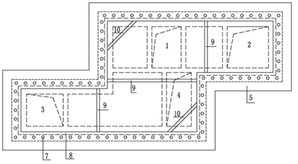
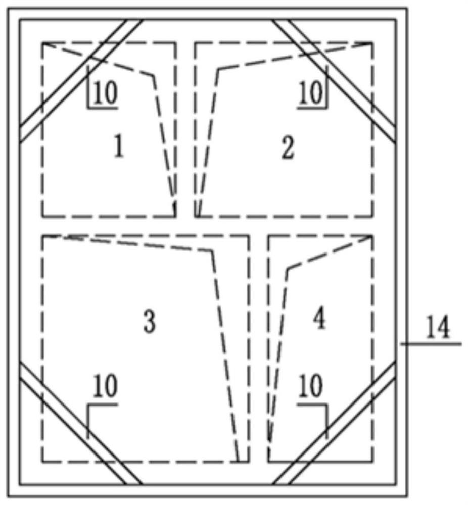
[0035] This embodiment provides a construction method for a special-shaped upside-down shaft wall in which the vertical shaft and the blow-out air shaft are built at the same time, and the method includes the following steps:

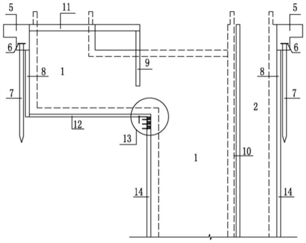
[0036] Step S1, three links and one leveling of the site, fence construction.

[0037] Step S2, setting the steel pipe pile 7, the bottom of the pile enters under the foundation pit of the blow-out wind shaft, and also serves as a temporary soil retaining member before the initial support 8 of the blow-out wind shaft is constructed.

[0038] Step S3, excavating a shallow foundation pit at the mouth, and molding the locking ring 5 structure.

[0039] Step S4, excavate the rock-soil body downwards by hanging...


PUM


Abstract

The invention provides a special-shaped upside-down hanging well wall construction method for simultaneously building a vertical shaft and a throwing-out air shaft. A steel pipe pile is driven, and the pile bottom enters the position below the foundation pit bottom of the throwing-out air shaft and serves as a temporary soil retaining component before primary support construction of the throwing-out air shaft; an opening shallow foundation pit is excavated, and an opening locking ring structure is molded; a rock-soil body is excavated downwards through a well wall upside down method, a throwing-out air shaft primary support is constructed, and throwing-out air shaft temporary section steel diagonal bracings and temporary section steel inclined bracings are erected; when excavation is conducted to the bottom elevation of the throwing-out air shaft foundation pit, a throwing-out air shaft foundation pit cushion layer is laid, and meanwhile a top cover plate is constructed to recover part of the construction site; the rock-soil body continues to be excavated downwards, a vertical shaft primary support and a temporary profile steel inclined strut are constructed, and an upper hanging and lower supporting structure is locally arranged on the first three steel frames of the vertical shaft primary support; and the vertical shaft continues to be excavated in a layering and blocking mode till the ingate holing elevation is reached, and steering air duct construction is prepared. Civil construction organization is convenient, and the mechanical work efficiency is high; and engineering materials are remarkably saved, and the civil engineering period is shortened.

Description

technical field [0001] The invention belongs to the technical field of urban rail transit engineering design and construction, and in particular relates to a construction method of a special-shaped upside-down shaft wall in which a vertical shaft and a blow-out air shaft are built simultaneously. Background technique [0002] Due to the functional requirements of urban subways, ventilation shafts are often installed at both ends of the station. Considering that the layout of the air shafts matches the surrounding environment and urban planning, the layout of the air shafts thrown out of the low wind pavilions is usually used to avoid the height of the wind pavilions. If it is too high, it will affect the perspective and layout pattern of the surrounding environment. Secondly, the wind shaft setting is relatively flexible and can be more easily realized in parallel with the planning. The urban construction layout is more reasonable and more solemn; the typical construction cha...

Claims


Application Information

Patent Timeline
Patent Type & Authority Applications(China)
IPC IPC(8): E21D1/08E21D5/11E21D5/12
CPCE21D1/08E21D5/11E21D5/12Y02E10/20
Inventor 王文娟高鑫吴琦李清菲冯世杰刘鹏毕经东贺维国孙为东金若翃段悟哲吴昊
Owner CHINA RAILWAY TUNNEL SURVEY & DESIGN INST
Why Eureka
Try Eureka