
Fan rotating speed control method for avoiding control misalignment caused by sudden change of power output state

A technology of power output and fan speed, used in pump control, non-variable-capacity pumps, components of pumping devices for elastic fluids, etc. Effect

Pending Publication Date: 2022-03-15
SEA SONIC ELECTRONICS
View PDF2 Cites 0 Cited by
  • Summary
  • Abstract
  • Description
  • Claims
  • Application Information

AI Technical Summary

Problems solved by technology

[0003] The main purpose of the present invention is to solve the problem that the control of the fan is easily misaligned when the output state of the power supply changes suddenly.

Method used


Image

  • Fan rotating speed control method for avoiding control misalignment caused by sudden change of power output state
  • Fan rotating speed control method for avoiding control misalignment caused by sudden change of power output state
  • Fan rotating speed control method for avoiding control misalignment caused by sudden change of power output state

Examples


Embodiment Construction

[0052] Detailed description and technical contents of the present invention are as follows with regard to coordinating accompanying drawings now:

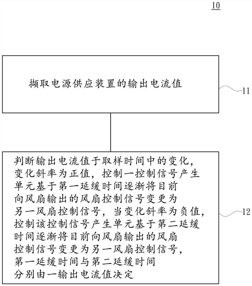
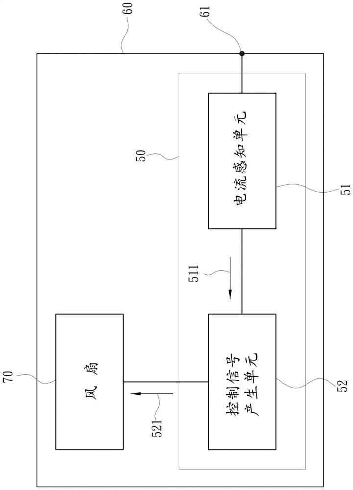
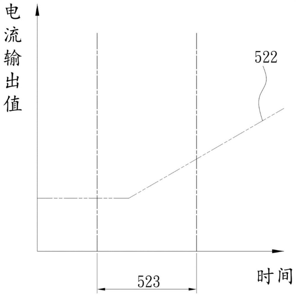
[0053] see Figure 1 to Figure 2 , the fan speed control method 10 of the present invention is used to avoid control inaccuracy caused by a sudden change in the output state of the power supply. In addition, the present invention will be described in detail later, and a fan driving circuit 50 implementing the fan speed control method 10 will be described later. The fan drive circuit 50 is set in a power supply device 60, the fan drive circuit 50 is used to control at least one fan 70 belonging to the power supply device 60, the fan drive circuit 50 includes a current sensing unit 51 and a control signal Generate unit 52 . Wherein, the current sensing unit 51 is electrically connected to the power supply device 60 and is disposed at an output end 61 of the power supply device 60, and the current sensing unit 51 is used to sense an...


PUM


Abstract

A fan rotating speed control method for avoiding control misalignment caused by sudden change of a power output state comprises the following steps: firstly, capturing an output current value of a power supply device, then judging the change of the output current value in a sampling time, controlling a control signal generating unit to gradually change a fan control signal currently output to a fan into another fan control signal based on a first delay time when the change slope is a negative value; and controlling the control signal generating unit to gradually change the fan control signal currently output to the fan into another fan control signal based on second delay time, wherein the first delay time and the second delay time are respectively determined by the output current value.

Description

technical field [0001] The invention relates to a method for controlling the rotational speed of a fan, in particular to a method for controlling the rotational speed of a fan which avoids control inaccuracy caused by a sudden change in the output state of a power supply. Background technique [0002] With the advancement of technology, fans on the market can adjust the speed according to the output state of the power supply device, that is, when the output current of the power supply device rises, the fan speed increases accordingly, and when the output current of the power supply device decreases, the fan speed decreases accordingly . In addition, the existing fan speed changes immediately with the output state of the power supply device, as disclosed in patents such as TW 201422128A and TW 200826813A in Taiwan, China. However, in the prior art, when the output state of the power supply device changes suddenly, the fan speed may be delayed due to signal transmission betwe...

Claims


Application Information

Patent Timeline
Patent Type & Authority Applications(China)
IPC IPC(8): F04D25/08F04D27/00F04D29/00
CPCF04D27/004F04D25/08F04D27/001F04D29/002
Inventor 张修诚周胜千吴威震
Owner SEA SONIC ELECTRONICS
Learn More