Power transmission line fault remote tester

A transmission line and long-distance technology, which is applied in the field of transmission line fault long-distance tester, can solve the problems of inconvenience, too long signal transmission line, etc., and achieve the effect of avoiding too fast lifting, not easy to shift, and convenient fixing

Inactive Publication Date: 2022-03-15
尚英玮
View PDF0 Cites 1 Cited by
  • Summary
  • Abstract
  • Description
  • Claims
  • Application Information

AI Technical Summary

Problems solved by technology

[0003] The cable fault detector is a set of comprehensive cable fault detection equipment, which can test the high resistance flashover fault, high and low resistance grounding, short circuit, cable disconnection, poor contact and other faults of the cable. Safe, rapid and accurate, high test accuracy, high degree of intelligence, waveform and parameter storage and recall function, dual trace display function, waveform expansion ratio function, can change the position of the double cursor arbitrarily and directly display the direct distance between the fault point and the test point or Relative distance, the function of modifying the propagation speed at any time according to different tested cables, and the excellent characteristics of small volume and portable appearance; the existing long-distance tester for transmission line faults has the problem that the signal transmission line is too long to be retractable and inconvenient

Method used


Image

  • Power transmission line fault remote tester
  • Power transmission line fault remote tester
  • Power transmission line fault remote tester

Examples


Embodiment Construction

[0027] Embodiments of the present patent are described in detail below, examples of which are shown in the drawings, wherein the same or similar reference numerals designate the same or similar elements or elements having the same or similar functions throughout. The embodiments described below by referring to the figures are exemplary and are only used for explaining the patent, and should not be construed as limiting the patent.

[0028] In the description of this patent, it is to be understood that the terms "center", "upper", "lower", "front", "rear", "left", "right", "vertical", "horizontal", The orientation or positional relationship indicated by "top", "bottom", "inner", "outer", etc. is based on the orientation or positional relationship shown in the drawings, and is only for the convenience of describing this patent and simplifying the description, rather than indicating or implying References to devices or elements must have a particular orientation, be constructed, ...


PUM


Abstract

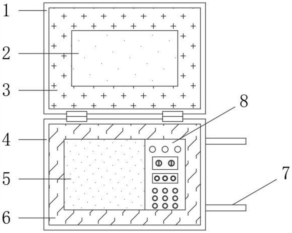
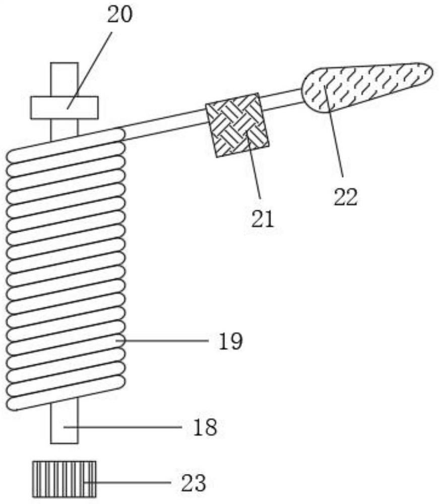
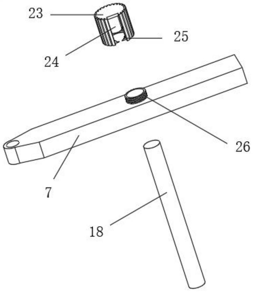
The invention belongs to the technical field of power maintenance, particularly relates to a power transmission line fault remote tester, and provides the following scheme for solving the problem that an existing signal transmission line is too long and inconvenient to fold and unfold, the power transmission line fault remote tester comprises a box body, hydraulic columns are fixedly installed on the four sides of the bottom end in the box body, and bodies are fixedly installed at the top ends of the hydraulic columns; a rubber ring is fixedly installed at the top end in the box body, the body is located in the rubber ring, storage grooves are formed in the two ends of the other side of the box body, and rotating plates are rotationally installed at the upper ends of the storage grooves. According to the invention, the two ends of the other side of the box body are provided with the storage grooves, and the upper ends of the storage grooves are rotatably provided with the rotating plates, so that when a worker inserts an insertion rod wound with a signal line between the two rotating plates, the insertion rod is stably and rotatably installed between the two rotating plates through the rotational connection of a positioning sleeve and a threaded outer ring and the magnetic attraction of a magnetic core and the insertion rod; and an overlong signal wire can be conveniently wound, so that the problem that the signal wire is placed disorderly and is inconvenient to use is solved.

Description

technical field [0001] The invention relates to the technical field of electric power maintenance, in particular to a remote tester for transmission line faults. Background technique [0002] The transmission line is implemented by using a transformer to boost the electric energy generated by the generator, and then connecting it to the transmission line through control equipment such as a circuit breaker. The transmission line can be divided into overhead transmission lines and cable lines according to the structural form; the basic process of power transmission is to create The conditions make the electromagnetic energy transmit along the direction of the transmission line, and the transmission capacity of the line is dominated by various laws of the electromagnetic field and the circuit; the test of the cable fault is based on the uneven impedance of the line when the electric wave is transmitted in the transmission line. principle. [0003] The cable fault detector is a...

Claims


Application Information

Patent Timeline
Patent Type & Authority Applications(China)
IPC IPC(8): G01R31/08
CPCG01R31/085
Inventor 尚英玮
Owner 尚英玮
Why Eureka
Try Eureka