Power transmission and transformation energy-saving device and power transmission and transformation system

An energy-saving device, power transmission and transformation technology, applied in the field of power transformation system, can solve problems such as major accidents, open fires that cannot be extinguished in time, and impact on residents' personal safety, so as to achieve the effect of improving safety

Pending Publication Date: 2022-03-15
钟德容
View PDF0 Cites 0 Cited by
  • Summary
  • Abstract
  • Description
  • Claims
  • Application Information

AI Technical Summary

Problems solved by technology

[0005] The present invention provides an energy-saving device for power transmission and transformation and a power transmission and transformation system. One of the purposes is to have the function of automatic fire extinguishing, so as to solve the problem that an open fire cannot be extinguished in time and may cause a bigger accident; the other purpose is to Solve the problem that the internal leakage of the residential grid centralized device will affect the personal safety of nearby residents, so as to achieve the effect of detecting and alarming the leakage information

Method used


Image

  • Power transmission and transformation energy-saving device and power transmission and transformation system
  • Power transmission and transformation energy-saving device and power transmission and transformation system
  • Power transmission and transformation energy-saving device and power transmission and transformation system

Examples


Embodiment 1

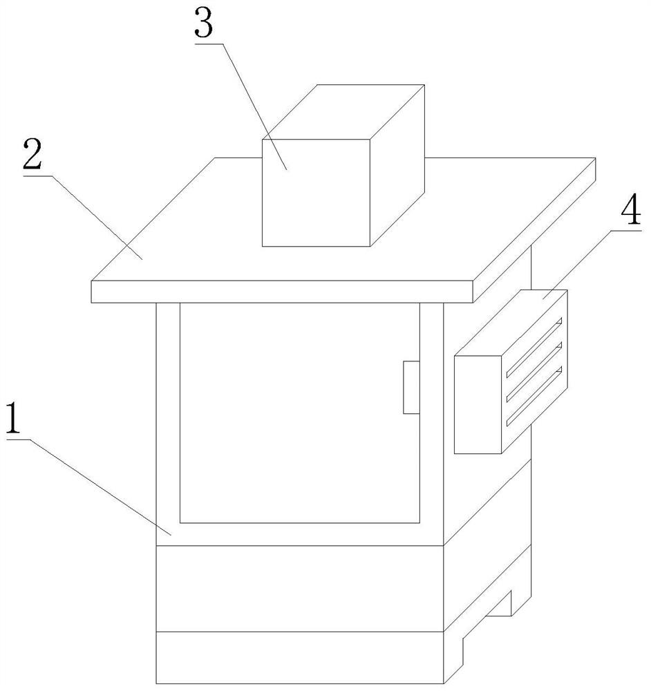
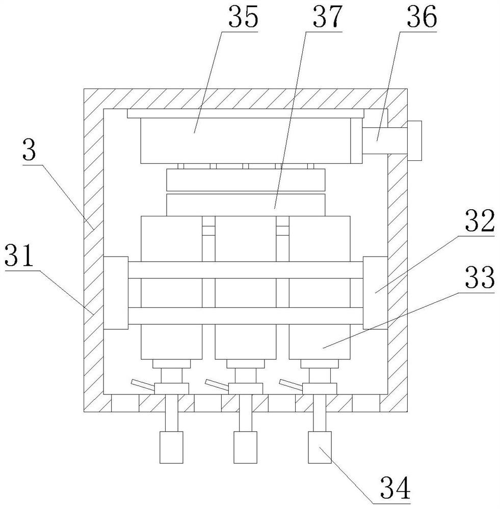
[0038] First aspect, such as Figure 1-9As shown, the present invention provides a power transmission and transformation energy-saving device, which includes a power control box 1, a body of the power transmission and transformation energy-saving device is fixedly installed in the inner cavity of the power control box 1, and the top of the power control box 1 is fixedly installed There is a sun visor 2, the top of the electric control box 1 is provided with an automatic fire extinguishing mechanism 3, and the right side of the electric control box 1 is provided with a ventilation mechanism 4, and the automatic fire extinguishing mechanism 3 includes a plastic box 31, on the inner wall of the plastic box 31 A support frame 32 is fixedly installed, and the inner wall of the support frame 32 is slidably connected with a push-type carbon dioxide fire extinguisher body 33. Two adjacent support frames 32 are fixedly connected by a connecting block, and the top of the support frame 32...

Embodiment 2

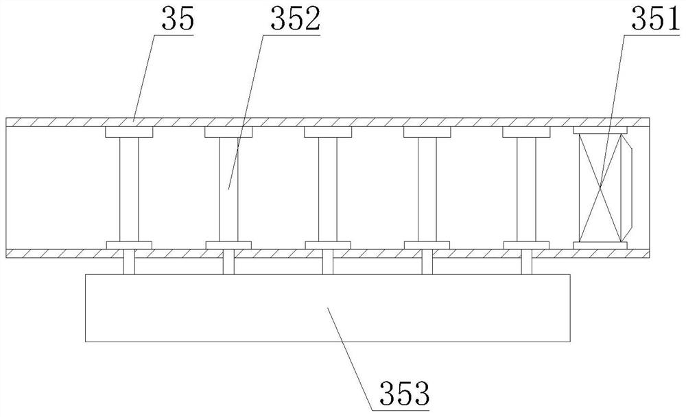
[0040] Such as Figure 1-9 As shown, on the basis of Embodiment 1, the present invention provides a technical solution: preferably, the plastic box 31 is fixedly connected to the top of the electric control box 1, and the top of the inner cavity of the plastic box 31 is fixedly installed with a control box body 35, the right side of the control box body 35 is detachably connected with an external discharge pipe 36, and the right side of the external discharge pipe 36 extends to the right side of the plastic box body 31, and the output end of the push type carbon dioxide fire extinguisher body 33 is fixedly connected with a cover type Nozzle 34, ventilation fan 351 is fixedly installed in the cavity of control box body 35, the top of control box body 35 cavity is fixedly installed with fixed plate 352, and the left side of fixed plate 352 is provided with air inlet slot 3521, and fixed plate 352 The right side of the air intake slot 3521 is provided with a discharge slot 3525, ...

Embodiment 3

[0042] Such as Figure 1-9 As shown, on the basis of Embodiment 1, the present invention provides a technical solution: preferably, the dehumidification box 41 is fixedly installed on the right side of the electrical control box 1, and a guide is fixedly installed in the inner cavity of the dehumidification box 41. Plate 43, the mobile end of electric telescopic rod 45 is fixedly installed with dehumidification plate 46, can detect the air humidity outside control electric cabinet 1 by air humidity sensor 44, when air humidity is comparatively dry, air humidity sensor 44 just controls electric The telescopic rod 45 is stretched, and the dehumidification plate 46 is pushed to the top of the dehumidification box 41, and the cotton moisture-absorbing rod 4635 and activated carbon particles are naturally dried by natural wind, so as to ensure the normal operation of the dehumidification work of the device. The dehumidification plate The top of 46 is fixedly equipped with a rubber ...


PUM


Abstract

The invention discloses a power transmission and transformation energy-saving device and a power transmission and transformation system, and relates to the technical field of power transformation systems.The power transmission and transformation energy-saving device comprises an electricity control box body, a power transmission and transformation energy-saving device body is fixedly installed in an inner cavity of the electricity control box body, a sun shield is fixedly installed at the top of the electricity control box body, and an automatic fire extinguishing mechanism is arranged at the top of the electricity control box body; a ventilation mechanism is arranged on the right side of the electricity control box body, and the automatic fire extinguishing mechanism comprises a plastic box body. Through work of a ventilation fan, high-temperature air in an electricity control box body is driven to enter an inner cavity of a control box body, the high-temperature air makes full contact with a copper plate so that the copper plate can be heated, heat is transferred to a supporting film through a graphene heat absorption plate, the supporting film is heated to deform in a downward stretching mode, meanwhile, a movable balancing weight is promoted to move downwards, and the heat dissipation efficiency is improved. The pressing type carbon dioxide fire extinguisher body is pressed downwards, and liquefied carbon dioxide is sprayed out through the covering type spray pipe to extinguish open fire in the electricity control box body.

Description

technical field [0001] The invention relates to the technical field of power transformation systems, in particular to an energy-saving device for power transmission and transformation and a power transmission and transformation system. Background technique [0002] The transmission of current often leads to loss due to the heating of the line, so the voltage is increased through transformers during transmission to reduce the current to reduce heat loss. High voltage electricity is very dangerous, and the target electrical appliances do not need it With such a high voltage, it is necessary to reduce the voltage through power transformation. Since multiple power transformations are required in the process of current transmission, the transmission of current is called power transmission and transformation. In the process of power transmission and transformation, power transmission and transformation energy saving is required. device. There are following problems at prior art: ...

Claims


Application Information

Patent Timeline
Patent Type & Authority Applications(China)
IPC IPC(8): H02B1/46H02B1/48H02J13/00A62C3/16A62C37/48B01D53/26G01R31/52G01N33/00
CPCH02B1/46H02B1/48H02J13/00002H02J13/00006A62C3/16A62C37/48B01D53/261G01R31/52G01N33/0004
Inventor 钟德容
Owner 钟德容
Why Eureka
Try Eureka