
Compensation control circuit and control method of switching-type regulator and switching-type regulator

A compensation control and regulator technology, applied in the direction of adjusting electrical variables, control/regulation systems, instruments, etc., can solve problems such as slow response, low system bandwidth, poor system stability, etc., to achieve fast response and stability good sex effect

Pending Publication Date: 2022-03-15
JOULWATT TECH INC LTD
View PDF0 Cites 0 Cited by
  • Summary
  • Abstract
  • Description
  • Claims
  • Application Information

AI Technical Summary

Problems solved by technology

[0003] In the above control process, the rising slope and falling slope of the inductor current have a great impact on the stability of the system. For example, when the slope rises or falls slowly, the system is more sensitive to noise, resulting in unstable system stability. Well, the existing technology only reduces the impact of noise by superimposing a ramp signal on the basis of sampling the inductor current during the rising phase of the inductor current. The noise impact during the falling phase is not resolved, or the existing technology superimposes the ramp signal at the beginning of the switching cycle , premature superimposition of the ramp signal will lead to lower system bandwidth and slower response

Method used


Image

  • Compensation control circuit and control method of switching-type regulator and switching-type regulator
  • Compensation control circuit and control method of switching-type regulator and switching-type regulator
  • Compensation control circuit and control method of switching-type regulator and switching-type regulator

Examples


Embodiment Construction

[0038] Preferred embodiments of the present invention will be described in detail below with reference to the accompanying drawings, but the present invention is not limited to these embodiments. The present invention covers any alternatives, modifications, equivalent methods and schemes made within the spirit and scope of the present invention.

[0039] In order to provide the public with a thorough understanding of the present invention, specific details are set forth in the following preferred embodiments of the present invention, but those skilled in the art can fully understand the present invention without the description of these details.

[0040] In the following paragraphs the invention is described more specifically by way of example with reference to the accompanying drawings. It should be noted that all the drawings are in simplified form and use inaccurate scales, which are only used to facilitate and clearly assist the purpose of illustrating the embodiments of t...


PUM


Abstract

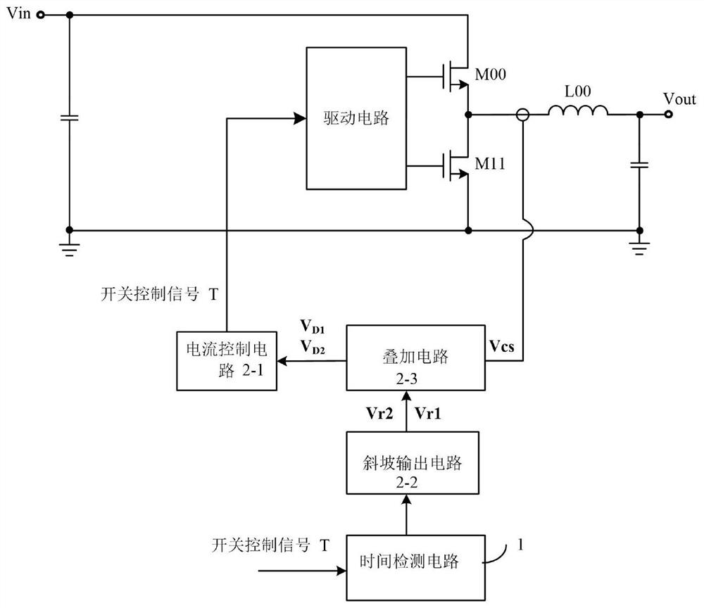
The invention discloses a compensation control circuit and a compensation control method for a switch-type regulator and the switch-type regulator, and the compensation control circuit comprises the steps: detecting the conduction time information of a switch control signal of a switch tube, so as to achieve the compensation of the switch tube under the condition that the conduction time ratio meets a threshold value; the slope compensation signal is superposed at the rising stage of the inductive current or the slope compensation signal is superposed at the falling stage of the inductive current, so that the influence of noise on the system is reduced under the condition that the response speed of the system is not influenced when the conduction time is relatively long in the whole switching period, and the switching type regulator system which is high in response speed and good in stability is obtained.

Description

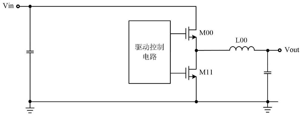
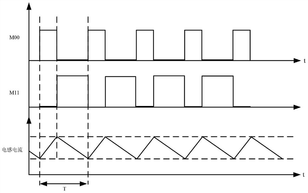
technical field [0001] The invention relates to the technical field of power electronics, and more specifically, relates to a compensation control circuit, a control method and a switching regulator of a switching regulator. Background technique [0002] In the control mode of switching power supply, the scheme of dual current control of peak current and valley current is often used in switching power supply, for example, as figure 1 As shown in the Buck switching power supply, the BUCK switching power supply includes a first switching tube M00, a second switching tube M11 and an inductor L00, wherein the first switching tube M00 and the second switching tube M11 are both MOS tubes, and Vin is a BUCK switch The input voltage of the power supply, Vout is the output voltage of the BUCK switching power supply. During the working process, when the first switch tube M00 is turned on, the current of the inductor L00 rises; when the first switch tube M00 is turned off, and the seco...

Claims


Application Information

Patent Timeline
IPC IPC(8): H02M3/158H02M1/08H02M1/088
CPCH02M3/158H02M1/08H02M1/088Y02B70/10
Inventor 窦训金黄必亮
Owner JOULWATT TECH INC LTD
Learn More