
Polishing disk trimming device of polishing machine

A dressing device and polishing disc technology, which is applied to the parts of grinding machine tools, grinding/polishing equipment, abrasive surface adjustment devices, etc., can solve the problems of increased load, high equipment cost, increased motor power, etc. Equipment operation mode, optimizing equipment energy consumption, reducing the effect of rotational inertia

Pending Publication Date: 2022-03-18
莱玛特·沃尔特斯(沈阳)精密机械有限公司
View PDF8 Cites 0 Cited by
  • Summary
  • Abstract
  • Description
  • Claims
  • Application Information

AI Technical Summary

Problems solved by technology

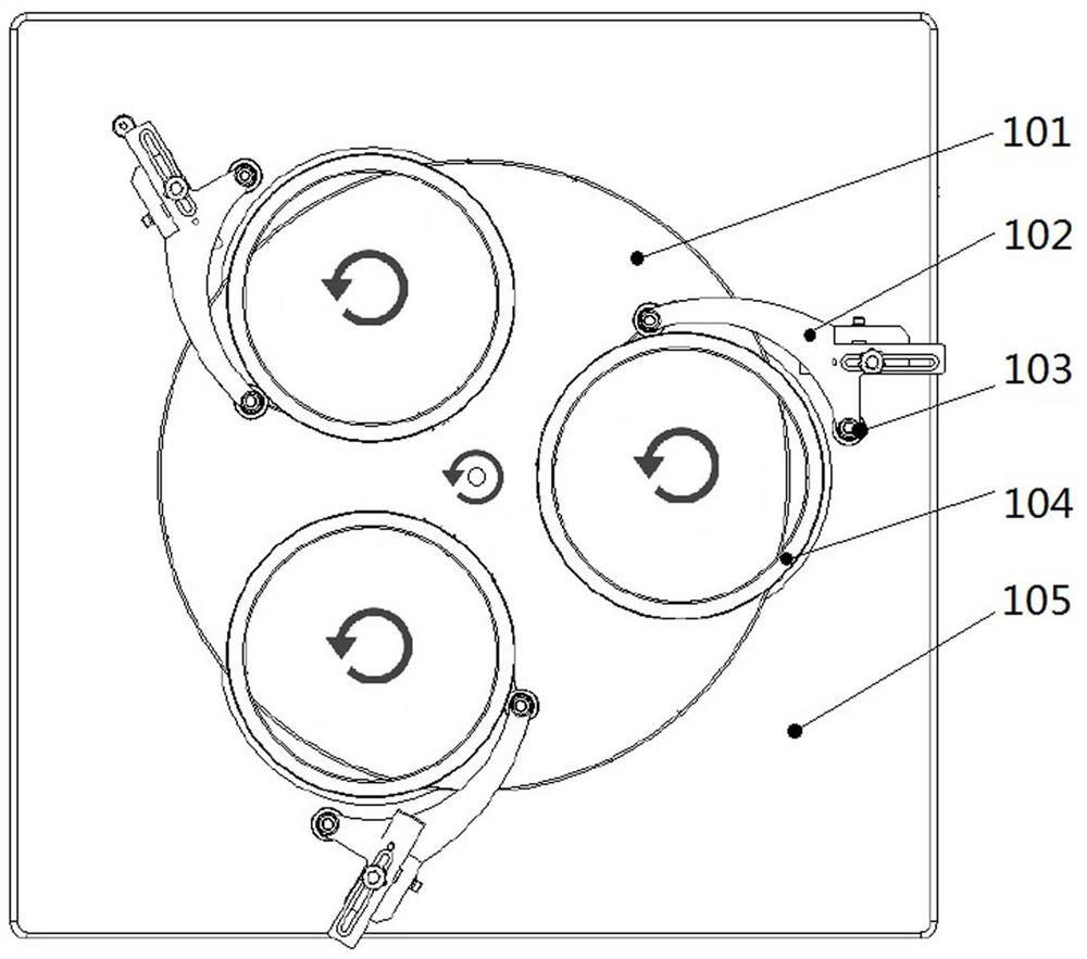
[0004] like figure 1 As shown, the existing dressing mechanism utilizes the self-weight of the annular dressing wheel 104 to carry out relative running friction with the rotating polishing disc 101 to complete the disc surface dressing of the polishing disc 101. If you want to change the dressing strength, you need to change the weight of the annular dressing wheel 104 , that is, the thickness size or material, this method of changing the dressing strength is cumbersome and costly; in addition, since the annular dressing wheel 104 needs to be placed on the polishing disc 101, it is equal to adding the weight of the annular dressing wheel 104 on the polishing disc 101 On the other hand, the load of the polishing disc 101 becomes larger, the rotational inertia of the polishing disc 101 is too large, and the rotational movement of the polishing disc 101 is unstable, which will affect the effect of the polishing process
Moreover, if the load of the polishing disc 101 is large, the power of the motor driven by it needs to be increased, the equipment cost is high, and the power consumption is large during use.

Method used


Image

  • Polishing disk trimming device of polishing machine
  • Polishing disk trimming device of polishing machine
  • Polishing disk trimming device of polishing machine

Examples


Embodiment Construction

[0033] The following examples are only specific examples of the present invention. In order to make the purpose, technical solutions and advantages of the present invention clear at a glance, the present invention will be described in further detail below in conjunction with the accompanying drawings and examples. The scope of protection of the present invention is not limited by the examples. limit.

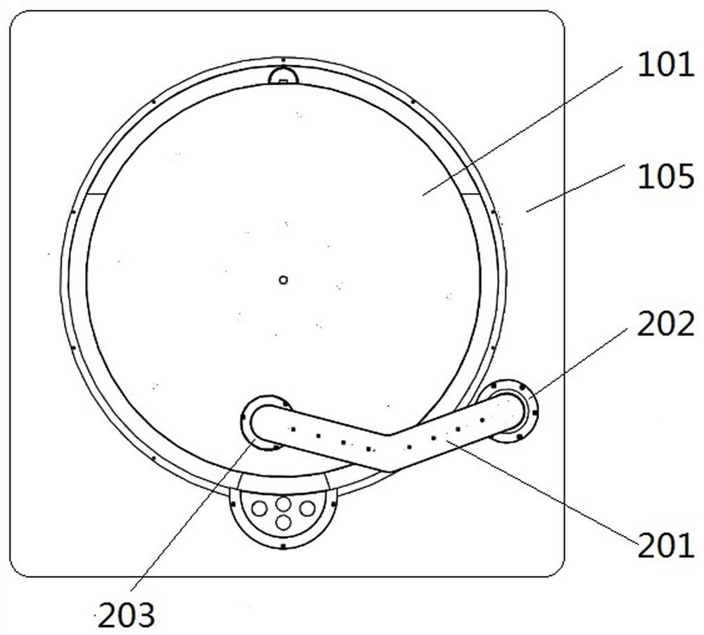
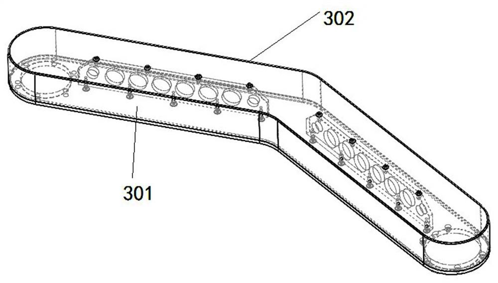
[0034] like figure 2 As shown, the present invention is a polishing disc dressing device for a polishing machine, which is composed of a rotating arm assembly 201 , a driving assembly 202 and a disc dressing spindle assembly 203 . The driving assembly 202 is fixed on the workbench 105 by screws uniformly distributed around the circumference, one end of the rotating arm assembly 201 is fixed on the rotating flange 412 of the driving part 202 by the screws uniformly distributed around the circumference, and the other end of the rotating arm assembly 201 is fixed on the rotating f...


PUM


Abstract

The invention discloses a polishing disk trimming device of a polishing machine, and belongs to the technical field of polishing equipment. A polishing disk trimming device of a polishing machine is composed of a rotating arm assembly (201), a driving assembly (202) and a disk trimming main shaft assembly (203). The driving assembly (202) is fixed to a workbench on the outer side of a polishing disk of the polishing machine through screws evenly distributed on the circumference, one end of the rotating arm assembly (201) is fixed to the driving assembly through screws evenly distributed on the circumference, and the disk repairing main shaft assembly (203) is fixed to the other end of the rotating arm assembly through screws evenly distributed on the circumference. According to the polishing disc finishing device, the finishing force of the polishing disc can be changed without manually replacing the finishing wheel, the maintenance time is shortened, the whole finishing mechanism is light in weight, the rotating inertia of the polishing disc is effectively reduced, and the polishing process is more stable.

Description

technical field [0001] The invention relates to a polishing disc dressing device of a polishing machine, which belongs to the technical field of polishing equipment. Background technique [0002] The polishing machine is a kind of polishing equipment. When polishing, the polishing disc rotates, and the workpiece is placed inside the annular dressing wheel set on the polishing disc. The workpiece and the dressing wheel do not rotate with the circumference of the polishing disc, but the annular dressing wheel can drive the workpiece inside it. Carry out self-rotation, use gravity to pressurize the workpiece, so that the workpiece and the polishing disc are rubbed against each other, so as to perform polishing processing, that is, when the parts are processed, the polishing disc is also trimmed at the same time. The dressing of the polishing disc is because after the polishing disc has been used for a period of time, the polishing agent used in the processing and the abrasive g...

Claims


Application Information

Patent Timeline
Patent Type & Authority Applications(China)
IPC IPC(8): B24B53/14B24B53/017
CPCB24B53/14B24B53/017
Inventor 姜玲玲杨申王英航张晓明王久辉刘立杰张启张闯
Owner 莱玛特·沃尔特斯(沈阳)精密机械有限公司
Learn More