
Mine drainage pipe positioning and mounting equipment

A positioning installation and drainage pipe technology, which is applied in the direction of workpiece clamping devices, workbenches, manufacturing tools, etc., can solve the problems of increased difficulty in positioning, damage to waterproof coating, and difficult alignment of installation, so as to reduce deviation and reduce work The effect of prolonging the amount and duration of use

Inactive Publication Date: 2022-03-18
危家其
View PDF0 Cites 0 Cited by
  • Summary
  • Abstract
  • Description
  • Claims
  • Application Information

AI Technical Summary

Problems solved by technology

The wellhead and the design target point are not on a vertical line, but deviate from the vertical line of the wellhead by a certain distance in a given direction according to human needs. Usually, the coal mines are inclined shafts, but the coal mines are in the process of mining. It will be accompanied by a large amount of groundwater seepage, so underground seepage water needs to be discharged continuously when mining coal mines underground, so drainage pipes need to be installed underground in coal mines. The method of installation, but because the drainage pipe is fixed on the wall of the mine, the range of activities of the staff is limited to a certain extent, which makes it difficult to align during installation. At the same time, because the drainage pipe is suspended in the air, there are bumps while moving Damage to the pipe wall of the drainage pipe leads to damage to the waterproof coating on its surface, and because the mine is inclined downward, it is necessary to prevent the drainage pipe from sliding during installation, which increases the difficulty of positioning

Method used


Image

  • Mine drainage pipe positioning and mounting equipment
  • Mine drainage pipe positioning and mounting equipment
  • Mine drainage pipe positioning and mounting equipment

Examples


Embodiment 1

[0036] A mine drainage pipe positioning and installation equipment, such as Figure 1-11 As shown, it includes a wheel 1, a vehicle frame 2, a support base 3, an adjustment mechanism 4, a fixing mechanism 5 and a positioning mechanism 6; a vehicle frame 2 is installed between the four wheels 1; four supports are installed at the bottom of the vehicle frame 2 The base 3; the inner bottom of the frame 2 is equipped with an adjustment mechanism 4; the adjustment mechanism 4 is located between the four support bases 3; the upper part of the adjustment mechanism 4 is equipped with a fixing mechanism 5; the left part of the adjustment mechanism 4 is equipped with a positioning mechanism 6.

[0037] Working principle: first move the mine drainage pipe positioning and installation equipment to the mine where the drainage pipe needs to be installed, then control the mine drainage pipe positioning and installation equipment to run and debug through the built-in power supply, control the ...

Embodiment 2

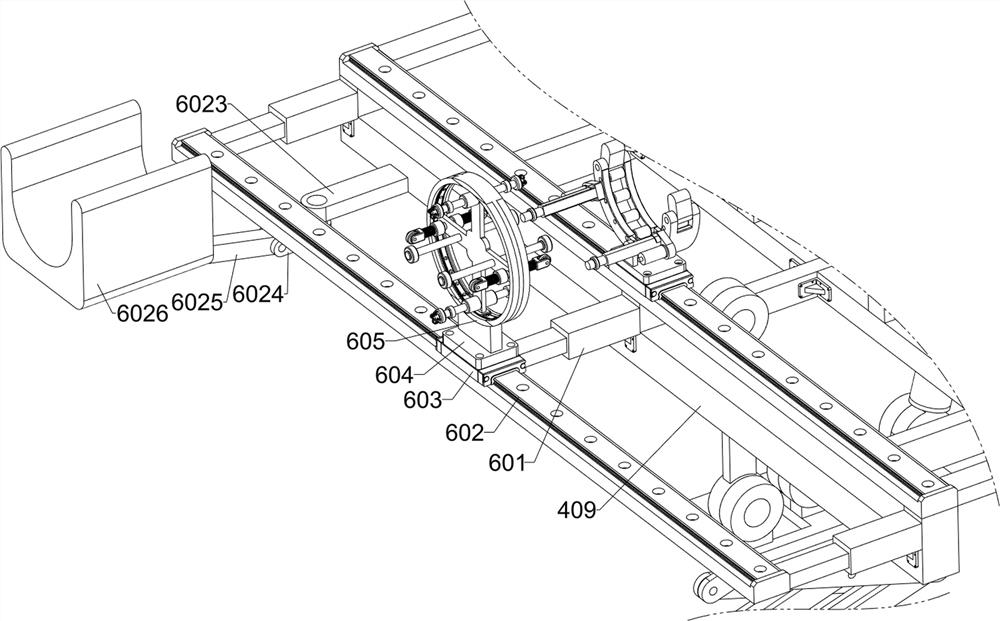
[0039] On the basis of Example 1, such as Figure 1-11 As shown, the adjustment mechanism 4 includes an electric turntable 401, a scissor frame 402, a first mounting plate 403, a first connecting plate 404, a first hydraulic push rod 405, a second hydraulic push rod 406, a second connecting plate 407, a first Three connecting plates 408 and brackets 409; the inner bottom of the vehicle frame 2 is fixedly connected with an electric turntable 401; the top of the electric turntable 401 is fixedly connected with a scissor frame 402; the top of the scissor frame 402 is fixedly connected with a first mounting plate 403; The left part of a mounting plate 403 is hinged with a first connecting plate 404; the middle part of the first mounting plate 403 is hinged with a first hydraulic push rod 405; the right part of the first mounting plate 403 is hinged with a second hydraulic push rod 406; The top of the hydraulic push rod 406 is hinged with a second connecting plate 407; the top of t...

Embodiment 3

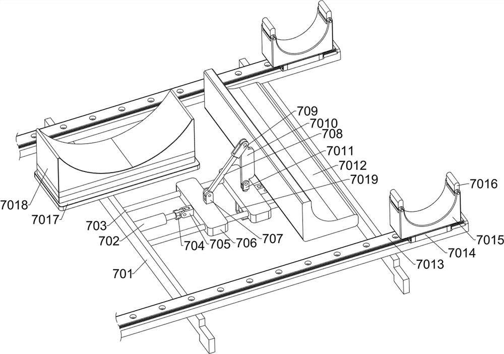
[0049] On the basis of Example 2, such as Figure 1-3 with Figure 12-14 As shown, a transportation mechanism 7 is also included; a transportation mechanism 7 is installed on the top of the adjustment mechanism 4; a transportation mechanism 7 is installed on the top of the fixing mechanism 5; the transportation mechanism 7 includes a seventh connecting plate 701, a second electric push rod 702, The second slide bar 703, the eighth connecting plate 704, the first bearing seat 705, the fourth slider 706, the second bearing seat 707, the ninth connecting plate 708, the third bearing seat 709, the tenth connecting plate 7010, the fourth Bearing seat 7011, L-shaped fixed seat 7012, fourth slide rail 7013, fifth slider 7014, second U-shaped fixed seat 7015, second limit block 7016, second mounting plate 7017, telescopic seat 7018 and third electric Push rod 7019; the upper part of the bracket 409 is fixedly connected with two seventh connecting plates 701; the upper part of the bra...


PUM


Abstract

The invention relates to the field of drainage pipe installation, in particular to mine drainage pipe positioning and installing equipment. The technical problems that an inclined shaft is difficult to position, a pipe wall is prone to being damaged during moving, and a waterproof coating on the surface of the pipe wall is damaged are solved. According to the technical scheme, the mine drainage pipe positioning and mounting equipment comprises wheels, a frame, a supporting base, an adjusting mechanism and the like; a frame is mounted among the four wheels; four supporting bases are mounted at the lower part of the frame; an adjusting mechanism for adjusting the angle of the drainage pipe is mounted at the inner bottom of the frame; the adjusting mechanism is located among the four supporting bases. Alignment adjustment of mine drainage pipes is achieved, meanwhile, the surfaces of flange plates connected with the drainage pipes and screw holes are cleaned, it is avoided that impurities left on the surfaces during drainage pipe connection affect connection firmness, and the defects that in the prior art, inclined shaft positioning is difficult, the pipe wall is prone to being damaged by knocking during movement, and the construction efficiency is high are overcome. And a waterproof coating layer on the surface is damaged.

Description

technical field [0001] The invention relates to the field of drainage pipe installation, in particular to a mine drainage pipe positioning installation device. Background technique [0002] Deviated well refers to a well with an inclined angle in drilling engineering. The wellhead and the design target point are not on a vertical line, but deviate from the vertical line of the wellhead by a certain distance in a given direction according to human needs. Usually, the coal mines are inclined shafts, but the coal mines are in the process of mining. It will be accompanied by a large amount of groundwater seepage, so underground seepage water needs to be discharged continuously when mining coal mines underground, so drainage pipes need to be installed underground in coal mines. The method of installation, but because the drainage pipe is fixed on the wall of the mine, the range of activities of the staff is limited to a certain extent, which makes it difficult to align during in...

Claims


Application Information

Patent Timeline
IPC IPC(8): B25H1/16B25B11/00
CPCB25H1/16B25B11/00
Inventor 危家其
Owner 危家其
Features
  • Generate Ideas
  • Intellectual Property
  • Life Sciences
  • Materials
  • Tech Scout
  • Unparalleled Data Quality
  • Higher Quality Content
  • 60% Fewer Hallucinations
Learn More