
In-vitro pump-free tissue culture chip based on microfluidic technology

A microfluidic technology and tissue culture technology, applied in the field of in vitro pump-free tissue culture chips, can solve the problems of increasing the threshold of use and cost, and achieve the effect of convenient preparation and simple operation

Pending Publication Date: 2022-03-18
DALIAN INST OF CHEM PHYSICS CHINESE ACAD OF SCI
View PDF0 Cites 0 Cited by
  • Summary
  • Abstract
  • Description
  • Claims
  • Application Information

AI Technical Summary

Problems solved by technology

[0004] Although microfluidic chips provide a powerful tool for tissue dynamic culture, the fluids of conventional chips need to be driven by external pump valves, which undoubtedly increases the threshold and cost of use

Method used


Image

  • In-vitro pump-free tissue culture chip based on microfluidic technology
  • In-vitro pump-free tissue culture chip based on microfluidic technology

Examples


Embodiment 1

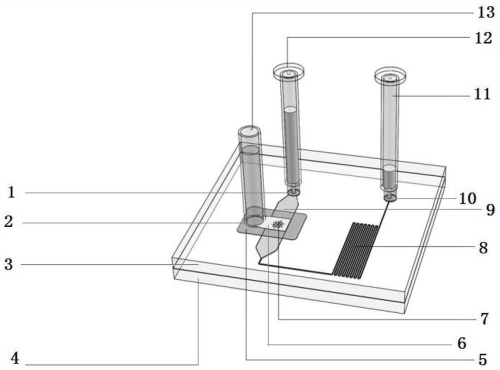
[0023] Such as figure 1 , the chip of this embodiment includes an upper chip 3 and a lower chip 4, and the upper chip 3 is arranged above the lower chip 4; the surface of the lower chip 4 is provided with a groove-shaped chamber passage 9, and the chamber passage One end of 9 is connected with the inlet 1, and the culture solution enters the chamber channel 9 through the inlet 1, and the other end of the chamber channel 9 is connected with one end of the groove-shaped flow resistance channel 8, and the other end of the flow resistance channel 8 is connected with the outlet 10 connected; the upper chip 3 is provided with a tissue chamber 6 for placing the sample 7, the tissue chamber 6 is provided with a sample loading port 2, and the tissue chamber 6 is arranged above the chamber channel 9, A porous membrane 5 is provided between the tissue chamber 6 and the chamber channel 9 to support the sample 7; above the upper chip 3, a culture medium collection pool 11, a culture medium...

Embodiment 2

[0033] The sample 7 described in this embodiment is a mouse testis tissue, and the steps are as follows: put the mouse testis tissue into the tissue chamber 6, and connect the culture medium storage solution at the inlet 1 and the outlet 10 The pool 12 is connected to the medium collection pool 11 , and the medium balance pool 13 is connected to the sample loading port 2 of the tissue chamber 6 . An appropriate amount of medium is added to the medium storage tank 12, and the medium can flow into the medium balance tank 13 and the medium collection tank 11 driven by gravity. The liquid level in the medium balance tank 13 will soon be the same as the medium storage tank 12 , and then the medium will slowly flow into the medium collection tank 11 . This method needs to regularly add medium to the medium storage tank 12 and discard the medium in the medium collection tank 11 .

[0034] In 2011, Japanese scholar Takehiko Ogawa cultivated mouse testis tissue using an air-liquid int...


PUM

PropertyMeasurementUnit
Total lengthaaaaaaaaaa
Widthaaaaaaaaaa
Depthaaaaaaaaaa

Abstract

The invention discloses an in-vitro pump-free tissue culture chip based on a microfluidic technology, and belongs to the technical field of tissue culture. The chip comprises an upper-layer chip and a lower-layer chip, wherein the upper-layer chip is arranged above the lower-layer chip; a cavity channel and a flow resistance channel are arranged on the surface of the lower-layer chip, one end of the cavity channel is connected with the inlet, the other end of the cavity channel is connected with one end of the groove-shaped flow resistance channel, and the other end of the flow resistance channel is connected with the outlet; the upper-layer chip is provided with a tissue chamber for placing a sample, a sample loading opening is formed in the tissue chamber, the tissue chamber is arranged above the chamber channel, and a porous membrane is arranged between the tissue chamber and the chamber channel and is used for supporting the sample; a culture medium collecting pool, a culture medium liquid storage pool and a culture medium balancing pool are arranged above the upper-layer chip. The chip provided by the invention can realize dynamic flowing of the culture medium without a pump valve and an external pipeline, and is convenient to prepare and simple to operate.

Description

technical field [0001] The invention belongs to the technical field of tissue culture, and in particular relates to an in vitro pumpless tissue culture chip based on microfluidic technology. Background technique [0002] From drug design, discovery and safety analysis to clinical aspects of personalized medicine, suitable in vitro models are needed as testing tools to more accurately understand the biological basis of diseases and improve the accuracy of drug screening. Although the structure of isolated primary tissue is more complex and its function is closer to that of the body, compared with cell lines, primary tissue is difficult to maintain a longer culture time in vitro because it is out of the stable microenvironment in vivo. Tissues are exposed to physiological fluid conditions in vivo, while traditional static culture is difficult to provide a similar microenvironment. [0003] In recent years, microfluidic organ-on-a-chip technology has been continuously develope...

Claims


Application Information

Patent Timeline
IPC IPC(8): C12M3/00B01L3/00
CPCC12M21/08C12M23/16B01L3/5027
Inventor 秦建华郭雅琼
Owner DALIAN INST OF CHEM PHYSICS CHINESE ACAD OF SCI
Learn More