Unmanned aerial vehicle autonomous landing method based on vision assistance

A technology for unmanned aerial vehicle and ship landing, which is applied in the direction of non-electric variable control, instrument, height or depth control, etc. It can solve the problems that affect the accuracy of landing, high computational complexity, and affect the accuracy of landing, so as to ensure accurate control, The effect of high control precision and simple principle

Pending Publication Date: 2022-03-18
NAT UNIV OF DEFENSE TECH
View PDF4 Cites 2 Cited by
  • Summary
  • Abstract
  • Description
  • Claims
  • Application Information

AI Technical Summary

Problems solved by technology

[0004] 1. Positioning by GPS; when positioning a drone by GPS, it is difficult to achieve accurate landing due to its low positioning accuracy and often weak or interrupted signals; when guiding the drone to land by radar, it is easy to be affected Electromagnetic wave interference makes it invalid, and radar is expensive, which is not conducive to popularization
[0005] 2. The method realized by radar guidance is expensive and susceptible to electromagnetic wave interference, so it is not easy to promote
However, in the camera calibration process, there are often large errors in the calibration internal reference results, and the superposition of each parameter error will lead to a large deviation in the final relative position, thus affecting the landing accuracy
[0018] 2. When controlling the landing of the UAV through the image-based visual servo method, the scheme of Lee et al. needs to first construct an interaction matrix through the coordinates of the four corner points of the landing mark on the image, and then roughly estimate the depth information, so that Calculate the six speed control quantities of the drone, but this leads to high computational complexity
But when the height reaches 50 meters, ordinary landing signs are difficult to be recognized and detected
If only the image size is increased, when the UAV is close to the landing sign, the image will not be able to cover the entire landing sign due to the limited field of view of the camera, which will affect the precise landing of the UAV.
Moreover, most of the existing research on autonomous landing is based on static or horizontal movement of landing marks, and the ship is affected by wave motion when it is on the sea surface, resulting in constant changes in the pose of the landing mark, which is likely to affect the accuracy of landing

Method used


Image

  • Unmanned aerial vehicle autonomous landing method based on vision assistance
  • Unmanned aerial vehicle autonomous landing method based on vision assistance
  • Unmanned aerial vehicle autonomous landing method based on vision assistance

Examples


Embodiment Construction

[0083] The present invention will be further described in detail below in conjunction with the accompanying drawings and specific embodiments.

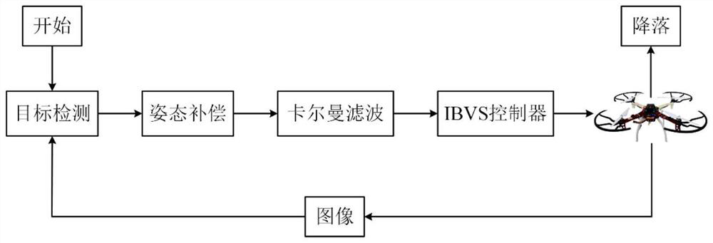
[0084] The invention adopts an image-based visual servo (IBVS) control method to realize the autonomous landing of the unmanned aerial vehicle on the sea surface ship. The entire control process does not need to calculate the position of the target relative to the UAV, but directly designs the control law on the image plane, thereby avoiding the deviation caused by the camera internal parameter calibration error in the position calculation process. System architecture such as figure 1 shown.

[0085] Such as figure 1 Shown, the UAV autonomous landing method based on vision aid of the present invention, it comprises:

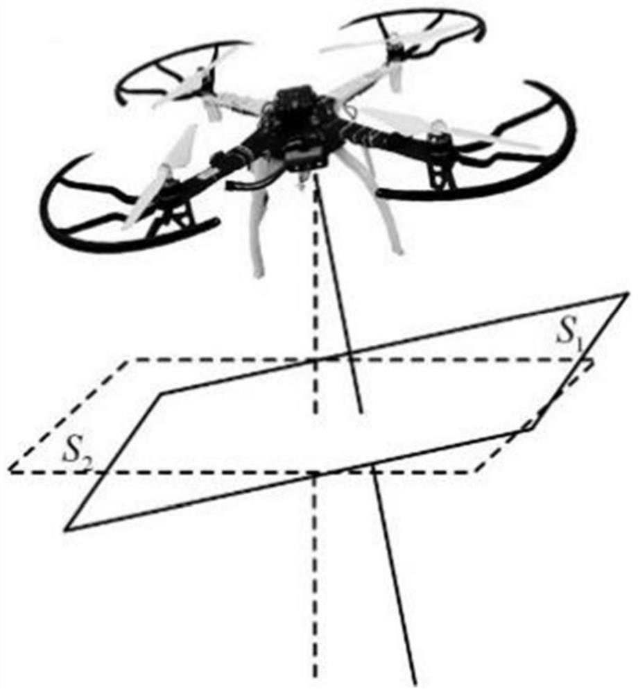
[0086] Step S1: Design the landing sign; select two different types of two-dimensional codes, and form the landing sign by nesting them (see Figure 5 );

[0087] Step S2: Take an image; the UAV first captures the i...


PUM


Abstract

The invention discloses an unmanned aerial vehicle autonomous carrier landing method based on vision assistance. The method comprises the steps that S1, a landing mark is designed; selecting two different types of two-dimensional codes, and forming a landing mark through nested placement; s2, taking an image; the unmanned aerial vehicle captures an image of a landing mark through a fixed down-looking camera; s3, obtaining a mark center coordinate; obtaining the coordinate of the landing mark center on the image by using a detection algorithm; s4, performing attitude compensation; the attitude change in the translation process of the unmanned aerial vehicle is eliminated through attitude compensation; s5, target prediction; introducing Kalman filtering to predict the position of the target on the image at the next moment in consideration of the real-time change of the pose of the landing mark; s6, landing is controlled; and the predicted coordinates are directly used as the input of the controller to realize the landing of the unmanned aerial vehicle. The method has the advantages of simple principle, high control precision, good reliability and the like.

Description

technical field [0001] The invention mainly relates to the technical field of unmanned aerial vehicles, in particular to a method for autonomously landing an unmanned aerial vehicle based on visual aids. Background technique [0002] When the landing of the rotor UAV is artificially controlled, due to unskilled operation and shaking, the UAV may roll over or fall, resulting in damage to the rotor and other components, and the accuracy of the landing largely depends on the operator's ability. proficiency level. In addition, the landing of drones on ships or sea ships will be disturbed by sea wind and ship shaking, which poses a higher challenge to precise landing. [0003] In order to solve this problem, it can be realized by the autonomous landing of the drone. In the current UAV landing scheme, generally include the following: [0004] 1. Positioning by GPS; when positioning a drone by GPS, it is difficult to achieve accurate landing due to its low positioning accuracy a...

Claims


Application Information

Patent Timeline
Patent Type & Authority Applications(China)
IPC IPC(8): G05D1/06
CPCG05D1/0676
Inventor 王祥科刘志宏杨凌杰俞先国相晓嘉王冠政胡新雨颜佳润习业勋
Owner NAT UNIV OF DEFENSE TECH
Why Eureka
Try Eureka