Plug-in method, device and system, storage medium and equipment

A plug-in and component technology, applied in the field of automatic plug-in of electronic components, can solve problems such as difficult to meet high-efficiency automation, plug-in action failure, PCB board damage, etc., to reduce the trouble of repeated adjustment of hardware and/or software, and reduce the trouble of repeated programming , Improve the effect of accuracy and stability

Pending Publication Date: 2022-03-18
ROBOTICS ROBOTICS LTD
View PDF0 Cites 1 Cited by
  • Summary
  • Abstract
  • Description
  • Claims
  • Application Information

AI Technical Summary

Problems solved by technology

[0003] However, with the development of technology, there are more and more types of pins for electronic components. Therefore, it is often difficult for customized equipment to adapt to changes in various situations. Every time you replace components and / or circuit boards, you need to reprogram, which is a waste of time. Time, increased cost, difficult to meet the needs of efficient automation
[0004] In addition, the existing automatic plug-in system often sets an image sensor at the bottom of the pin to take a bottom view of the pin, as shown in the figure, in the bottom view, only the insertion end of the pin is included, and only the pin is identified On the one hand, the position of the insertion end of the component itself will affect the accuracy of pin position recognition due to the different angles of the component itself; Due to the failure of the action, it may cause damage to the PCB board
[0005] In addition, for some artificial plug-ins, only a jack with a diameter of 0.6mm may be needed, because it needs to be realized by an automated method, and the diameter of the jack often needs to be enlarged to 1mm, and the extra space makes it easy for the pins to be biased after the plug-in is completed. , falling off, etc.

Method used


Image

  • Plug-in method, device and system, storage medium and equipment
  • Plug-in method, device and system, storage medium and equipment
  • Plug-in method, device and system, storage medium and equipment

Examples


Embodiment Construction

[0081] In order to make the purpose, technical solutions and advantages of the present application clearer, the present application will be described in further detail below in conjunction with the accompanying drawings and embodiments. It should be understood that the specific embodiments described here are only used to explain the present application, and are not intended to limit the present application.

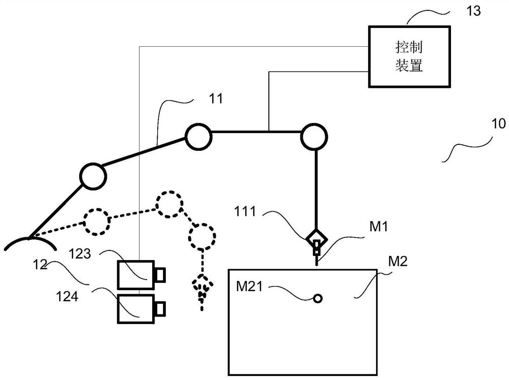
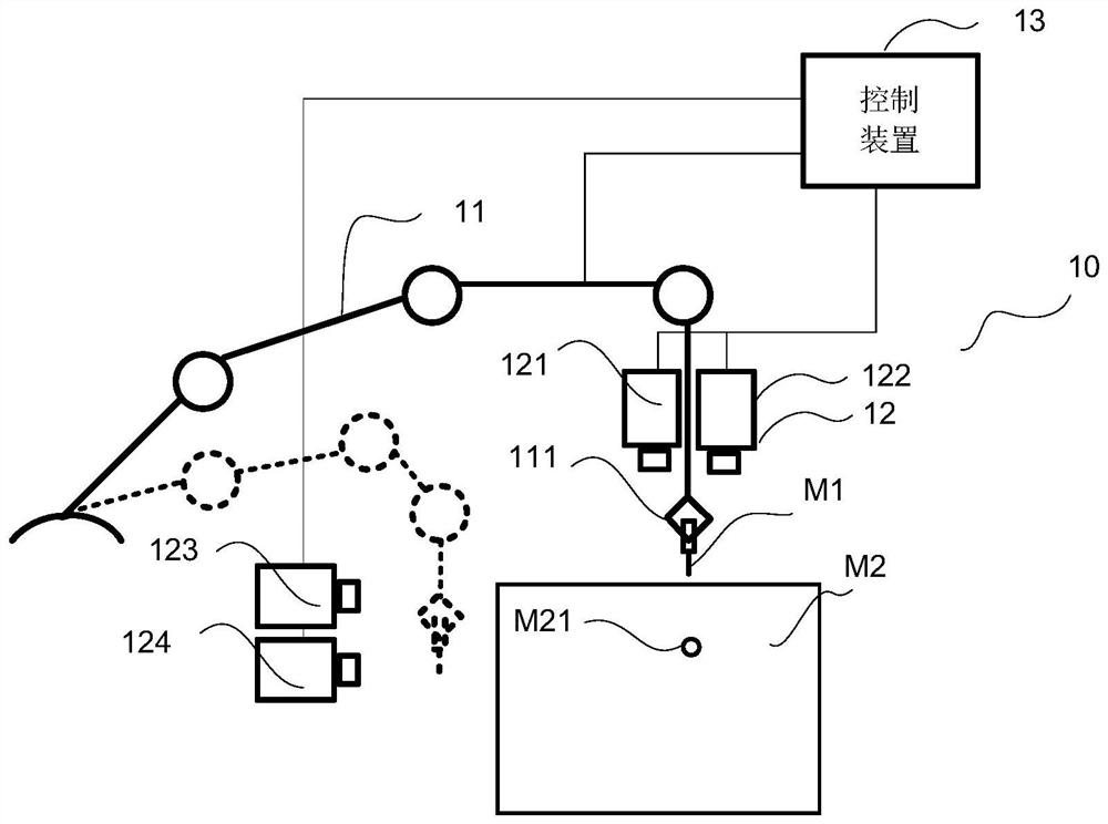
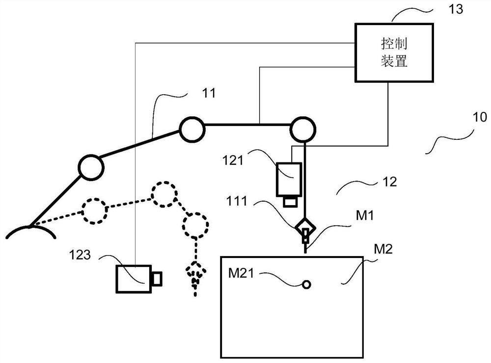
[0082] The plug-in method, device, system, storage medium, and equipment provided by the embodiments of the present invention can be applied to the technical field of automatic plug-in of electronic components. By identifying pin positions based on side views, more reference information can be provided for pin position identification. Improve the accuracy of pin position recognition, thereby improving the success rate of subsequent plug-ins.

[0083] Such as Figures 1A-1C As shown, the embodiment of the present invention provides a plug-in system 10 , and the system 10 ...


PUM


Abstract

The invention relates to a plug-in method, device and system, a storage medium and equipment. The plug-in method comprises the following steps: acquiring a side view of an element; the element is the element which is grabbed by an actuator; identifying a pin position of a pin based on the side view; the pin is the pin of the element; obtaining a jack position of the jack; and generating a control instruction based on the pin position and the jack position, and controlling an actuator to drive the pin to be inserted into the jack through the control instruction. According to the technical scheme, the pin position is identified based on the side view, so that the pin position identification precision is improved.

Description

technical field [0001] The present application relates to the field of automatic insertion of electronic components, in particular to an insertion method, device, system, storage medium and equipment. Background technique [0002] With the development of industrial automation, plug-in devices came into being. The plug-in device is used to automatically insert the pins of the electronic components into the sockets of the circuit board, thereby improving efficiency, product consistency, and saving labor costs. [0003] However, with the development of technology, there are more and more types of pins for electronic components. Therefore, it is often difficult for customized equipment to adapt to changes in various situations. Every time you replace components and / or circuit boards, you need to reprogram, which is a waste of time. Time and cost are increased, and it is difficult to meet the needs of efficient automation. [0004] In addition, the existing automatic plug-in sy...

Claims


Application Information

Patent Timeline
Patent Type & Authority Applications(China)
IPC IPC(8): G06T7/00G06T7/13G06T7/73G06N3/04G06N3/08
CPCG06T7/0004G06T7/13G06T7/73G06N3/08G06T2207/10004G06T2207/20081G06T2207/20084G06T2207/30148G06N3/045
Inventor 不公告发明人
Owner ROBOTICS ROBOTICS LTD
Why Eureka
Try Eureka