
Circuit board

A circuit board and circuit layer technology, which is applied in the direction of circuit devices, printed circuits, printed circuit components, etc., can solve problems such as signal reflection, affecting signal quality, and impedance discontinuity

Pending Publication Date: 2022-03-18
中科可控信息产业有限公司
View PDF0 Cites 0 Cited by
  • Summary
  • Abstract
  • Description
  • Claims
  • Application Information

AI Technical Summary

Problems solved by technology

However, the connector area or chip fan-out (Fan-out) area on the general circuit board is densely populated with vias, which cannot increase the wiring width. In these areas, only thin lines can be selected to ensure the fan-out of the wiring, while the fan-out of the connector or chip Outside the area (that is, the Open Field area), you can choose a wide line to control the loss. In this process, the design of the gradient line will appear, and the gradient line will appear as an impedance discontinuity point. When continuous, there will be signal reflection, jitter and other phenomena that affect the signal quality

Method used


Image

  • Circuit board
  • Circuit board
  • Circuit board

Examples


Embodiment Construction

[0050] The following will clearly and completely describe the technical solutions in the embodiments of the present application with reference to the drawings in the embodiments of the present application. Obviously, the described embodiments are part of the embodiments of the present application, not all of them. Based on the embodiments in this application, all other embodiments obtained by persons of ordinary skill in the art without creative efforts fall within the protection scope of this application.

[0051] The terms "first", "second", "third" and "fourth" in the specification and claims of the present application and the drawings are used to distinguish different objects, rather than to describe a specific order . Furthermore, the terms "include" and "have", as well as any variations thereof, are intended to cover a non-exclusive inclusion. For example, a process, method, system, product or device comprising a series of steps or units is not limited to the listed ste...


PUM


Abstract

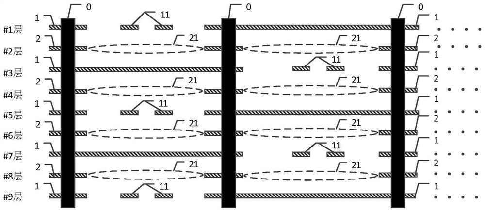
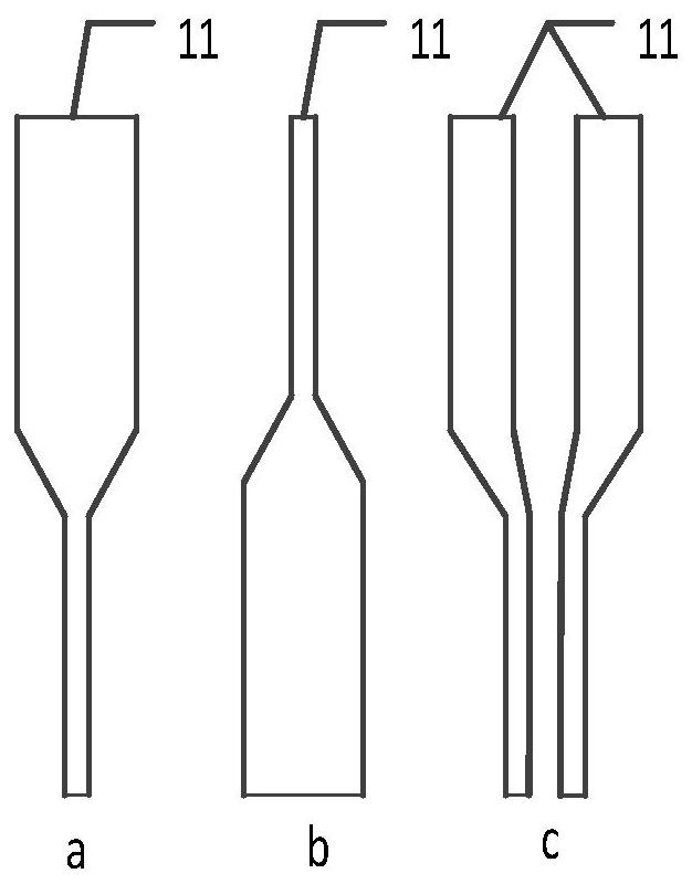
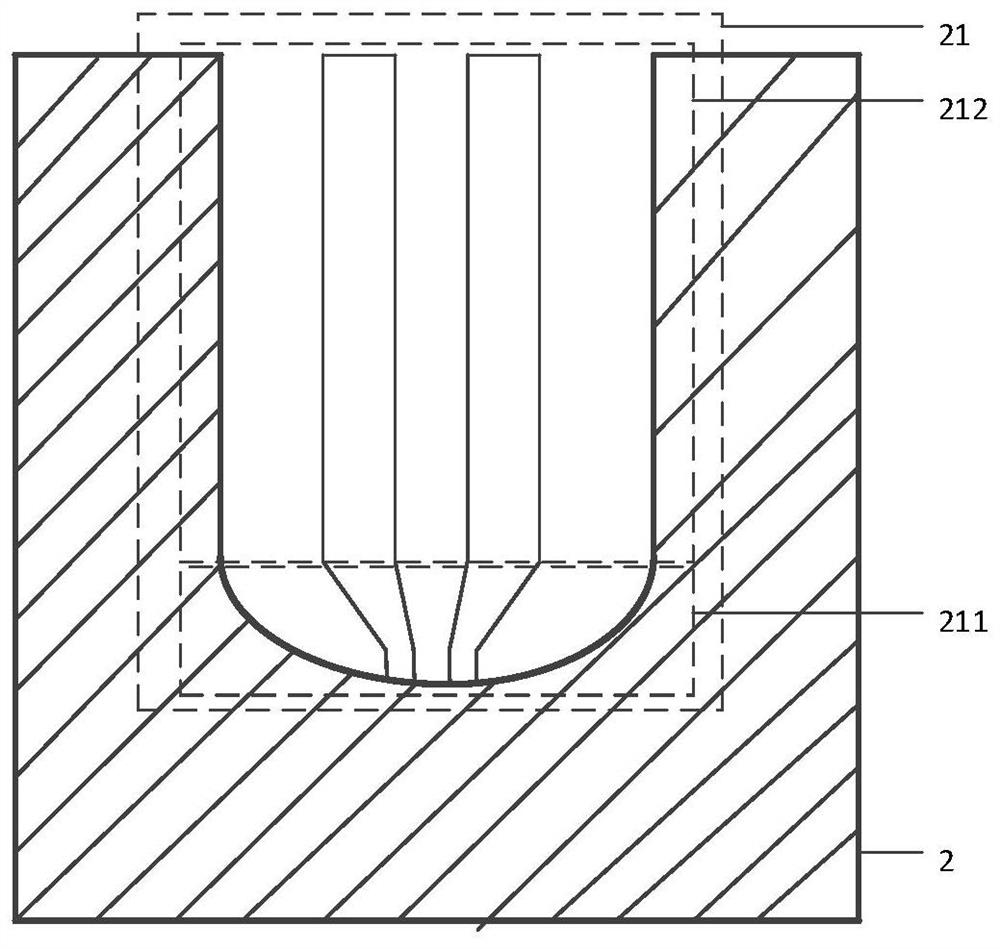
The invention relates to a circuit board, and the circuit board comprises at least one first circuit layer and at least one second circuit layer, the first circuit layer and the second circuit layer are arranged at an interval in the vertical direction, and the first circuit layer is provided with a gradual change signal line; the second circuit layer comprises a hollow area, and the position of the hollow area corresponds to the position of the gradual change signal line on the adjacent first circuit layer. Since the hollow area is hollowed according to the routing mode of the gradually-changed signal line on the first circuit layer, the thickness of the medium is increased, so that a thicker line width can be designed on the first circuit layer, and the purpose of reducing signal loss is achieved. Correspondingly, the impedance change of the area where the gradual change line signal is located can be minimized by optimizing the hollow area, so that the problem of discontinuous impedance of the gradual change line area is solved, and the quality of signal transmission on the circuit board is further improved.

Description

technical field [0001] The present application relates to the field of electronic technology, in particular to a circuit board. Background technique [0002] With the continuous development of electronic technology, especially the continuous development of high-speed signal technology, such as 32G two-level signal modulation technology (Non-Return-to-Zero, NRZ) and 56G four-level signal modulation technology (Pulse Amplitude Modulation, PAM4), while the requirements for signal quality are getting higher and higher. [0003] At present, for the routing of high-speed signal links, there is usually a problem that the routing length and routing path cannot be further optimized, which leads to a large signal loss. In order to reduce signal loss, wider traces can be designed in local areas on the circuit board to reduce signal loss. However, the connector area or chip fan-out (Fan-out) area on the general circuit board is densely populated with vias, which cannot increase the wi...

Claims


Application Information

Patent Timeline
IPC IPC(8): H05K1/02
CPCH05K1/024H05K1/025
Inventor 张军伟郭燕慧姜红兵黄建新邹小兵聂华
Owner 中科可控信息产业有限公司
Learn More