Active and passive integrated self-ligating bracket

A self-locking bracket, active and passive technology, applied in brackets, arch wires, etc., can solve the problems of not easy to fix, lock, pull off, etc., and achieve the effect of not easy to fall off, stable installation, and hard to fall.

Pending Publication Date: 2022-03-22
浙江益可森医疗科技有限公司
View PDF0 Cites 0 Cited by
  • Summary
  • Abstract
  • Description
  • Claims
  • Application Information

AI Technical Summary

Problems solved by technology

[0005] The present invention provides an active-passive integrated self-locking bracket, one of which is to have the function of preventing falling off and solve the problem of the

Method used


Image

  • Active and passive integrated self-ligating bracket
  • Active and passive integrated self-ligating bracket
  • Active and passive integrated self-ligating bracket

Examples


Embodiment 1

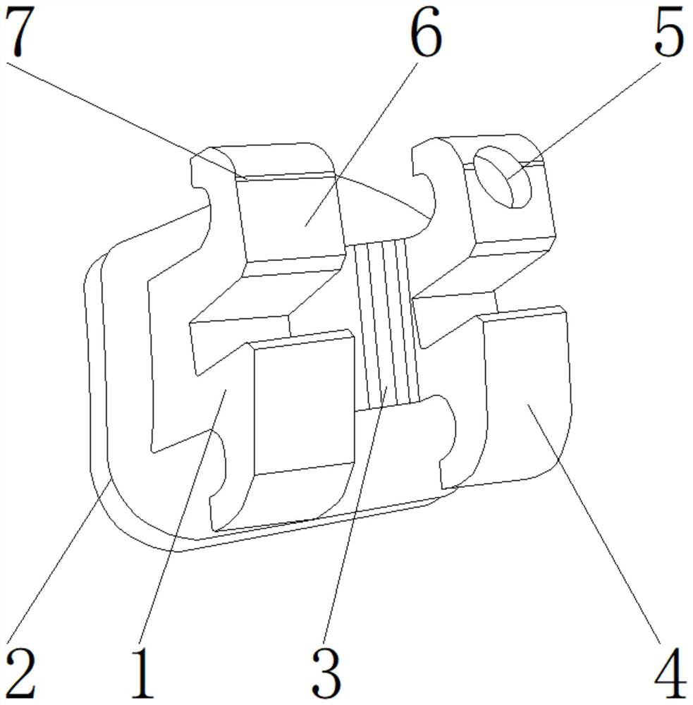
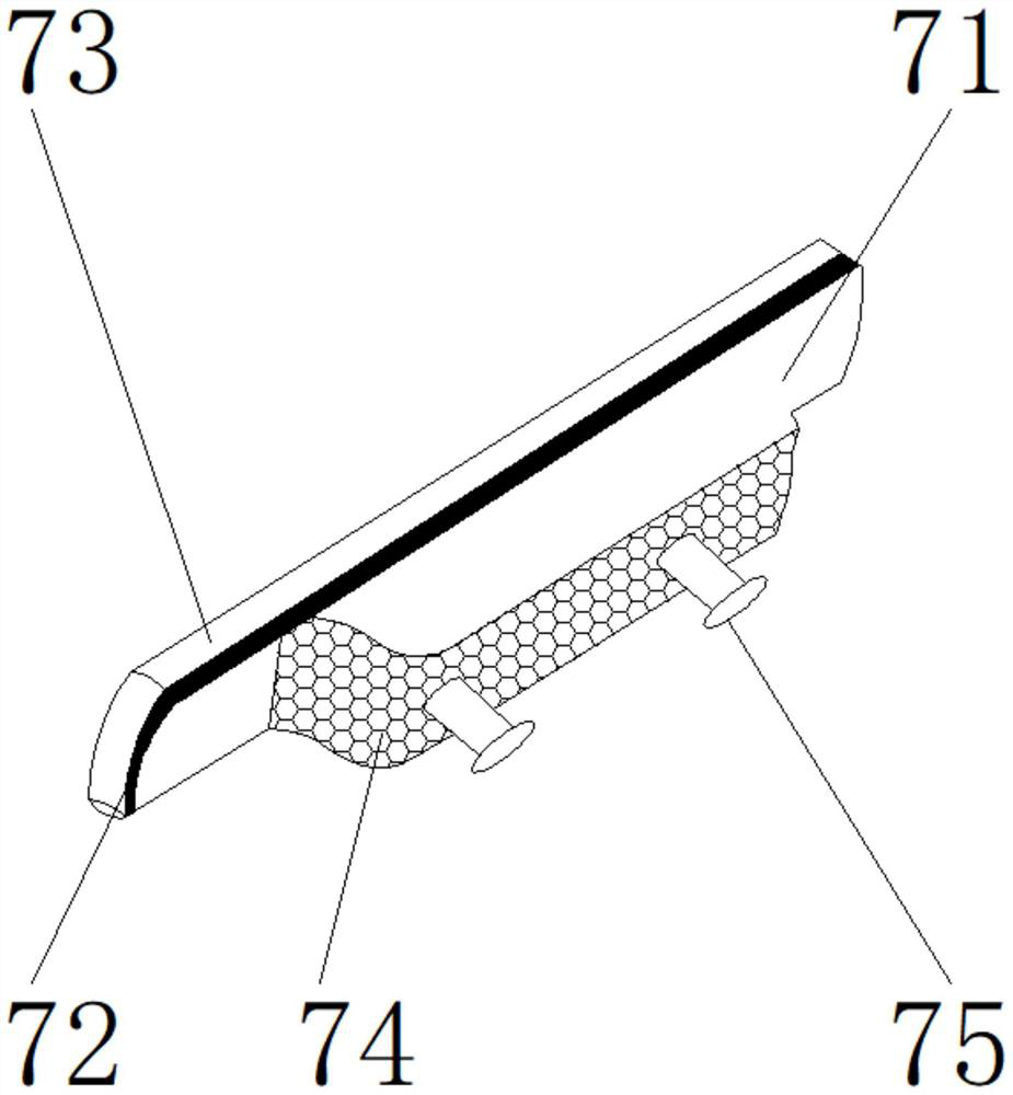
[0029] Such as Figure 1-5 As shown, the present invention provides an active and passive integrated self-locking bracket, comprising a main body 1, a base plate 2 is arranged at the lower end of the main body 1, a bracket body 6 is arranged at the upper end of the main body 1, and one side of the bracket body 6 is arranged There is a locking device 7, one side of the main body 1 is provided with an auxiliary device 3, one side of the auxiliary device 3 is provided with an elastic assembly 4, and the rear end of the elastic assembly 4 is provided with a fixing hole 5; the locking device 7 includes a locking plate 71, Adhesive strip 72, mounting plate 73, anti-corrosion coating 74, miniature screw 75, viscous strip 72 is positioned at the front end of mounting plate 73, and locking plate 71 is positioned at the front end of viscous strip 72; Between locking plate 71 and viscous strip 72 Superglue is provided, and the front end of the viscous strip 72 is fixedly connected to the...

Embodiment 2

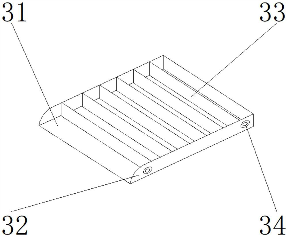
[0032] Such as Figure 1-5 As shown, on the basis of Embodiment 1, the present invention provides a technical solution: preferably, the auxiliary device 3 includes an arch wire slot 31, a side plate 32, an engaging mechanism 33, and a reed 34, and the engaging mechanism 33 is located on the arch wire. The upper end of the wire slot 31, the side plate 32 is located on both sides of the arch wire slot 31, the reed 34 is located on the outer surface of one side of the side plate 32, there is only a notch between the arch wire slot 31 and the engaging mechanism 33, the arch wire slot The upper end of 31 is detachably connected to the lower end of the engaging mechanism 33 through a notch, and a welding block is arranged between the side plate 32 and the arch wire slot 31, and one side of the side plate 32 is fixed to both sides of the arch wire slot 31 by the welding block To connect, a through hole is provided between the side plate 32 and the reed 34 , and one side of the reed 3...

Embodiment 3

[0035] Such as Figure 1-5As shown, on the basis of Embodiment 1, the present invention provides a technical solution: preferably, the engaging mechanism 33 includes an engaging plate 331, a guide bevel 332, a limit bar 333, a connecting hole 334, a buckle plate 335, and a guide The hypotenuse 332 is positioned at the rear end of the clamping plate 331, the buckle plate 335 is positioned at the front end of the clamping plate 331, the connection hole 334 is positioned at one side of the buckle plate 335, the limit bar 333 is positioned at one side of the clamping plate 331, and the clamping plate 331 and the guide inclined A welding block is arranged between the sides 332, and the front end of the guide hypotenuse 332 is fixedly connected with the rear end of the engaging plate 331 through the welding block, and a fixing bolt is arranged between the engaging plate 331 and the buckle plate 335, and the front end of the engaging plate 331 passes through the fixing bolt. It is fi...


PUM


Abstract

The invention discloses an active and passive integrated self-ligating bracket, and relates to the technical field of dental orthodontics, the active and passive integrated self-ligating bracket comprises a main body, the lower end of the main body is provided with a base plate, the upper end of the main body is provided with a bracket body, one side of the bracket body is provided with a locking device, and one side of the main body is provided with an auxiliary device; an elastic assembly is arranged on one side of the auxiliary device. Under the combined action of the arch wire groove, the side plate, the clamping mechanism and the reed, the bracket can be prevented from being pulled off from teeth due to excessive dental calculus in the teeth, the bracket can be clamped on the teeth, and under the combined action of the base, the elastic locking plate, the upper elastic cushion, the separation blade and the lower elastic cushion, the elasticity and the toughness of the bracket can be improved, so that the safety of the bracket is improved. According to the dental calculus bracket, the bracket cannot be damaged due to the effect of dental calculus, the locking capacity of the bracket can be improved under the combined action of a locking plate, a viscous adhesive tape, a mounting plate, an anti-corrosion coating and a micro screw, and the bracket can be stably connected with teeth.

Description

technical field [0001] The invention relates to the technical field of dental orthodontics, in particular to an active-passive integrated self-locking bracket. Background technique [0002] At present, during the orthodontic treatment of oral teeth, the orthodontic bracket is fixed on the tooth surface, the arch wire passes through the arch wire groove on the bracket, and the arch wire is directly ligated to the bracket by ligating a rubber ring or a steel wire On the ligated wing, the correcting force of the arch wire is transmitted to the teeth through the brackets, so that the teeth can move as expected, so as to achieve the purpose of correcting the teeth. There are following problems at prior art: [0003] 1. The existing active and passive integrated self-locking brackets are easy to loose and not easy to fix and lock; [0004] 2. The existing active and passive integrated self-locking brackets are easy to be pulled off from the teeth, and the reeds are easy to be pu...

Claims


Application Information

Patent Timeline
IPC IPC(8): A61C7/34
CPCA61C7/34
Inventor 濮佳明沈盛杰
Owner 浙江益可森医疗科技有限公司
Why Eureka
Try Eureka