Check patentability & draft patents in minutes with Patsnap Eureka AI!

Bridge construction method of full framing cast-in-place box girder

A technology for the construction of full support and bridges, which is applied in the direction of erecting/assembling bridges, bridges, bridge materials, etc., which can solve the problems of inconvenient construction process and achieve the effect of convenient preloading construction and high work efficiency

Inactive Publication Date: 2022-03-22
蒙书
View PDF0 Cites 0 Cited by
  • Summary
  • Abstract
  • Description
  • Claims
  • Application Information

AI Technical Summary

Problems solved by technology

[0002] The cast-in-place box girder of the full hall support is erected with dense formwork supports, and the box girder is cast in-situ. After the support is installed, hoist the pre-compression block to the pre-compression formwork support for pre-compression, measure the settlement of the formwork support, lift off the pre-compression block, measure the springback of the formwork support, and then install the prefabricated formwork on the formwork support, pour concrete, box After the concrete of the beam is solidified, the adjacent box girder is prestressed. During the whole process, because the supporting performance of the formwork support is extremely important, the inelastic deformation of the formwork support is eliminated by preloading, so as to ensure that the formwork support is on the bottom during the concrete pouring process. However, during the preloading process, the preloaded blocks need to be hoisted one by one to the cross arm on the formwork support and placed horizontally. After the preloading is completed, the preloaded blocks need to be hoisted one by one. The box girder is poured in multiple sections. For large-scale bridge construction sites, this preloading method is inconvenient in the actual construction process.

Method used


Image

  • Bridge construction method of full framing cast-in-place box girder
  • Bridge construction method of full framing cast-in-place box girder
  • Bridge construction method of full framing cast-in-place box girder

Examples


Embodiment Construction

[0026] The following will clearly and completely describe the technical solutions in the embodiments of the present invention with reference to the drawings in the embodiments of the present invention.

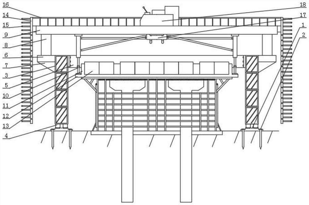
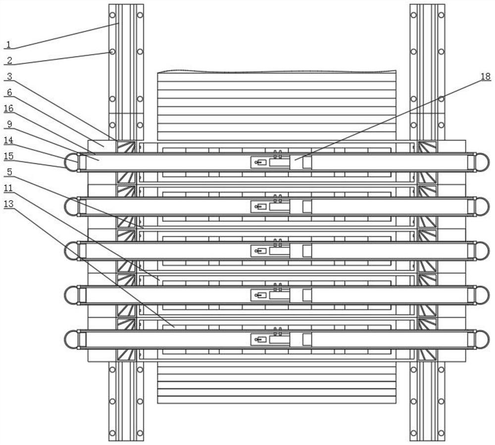
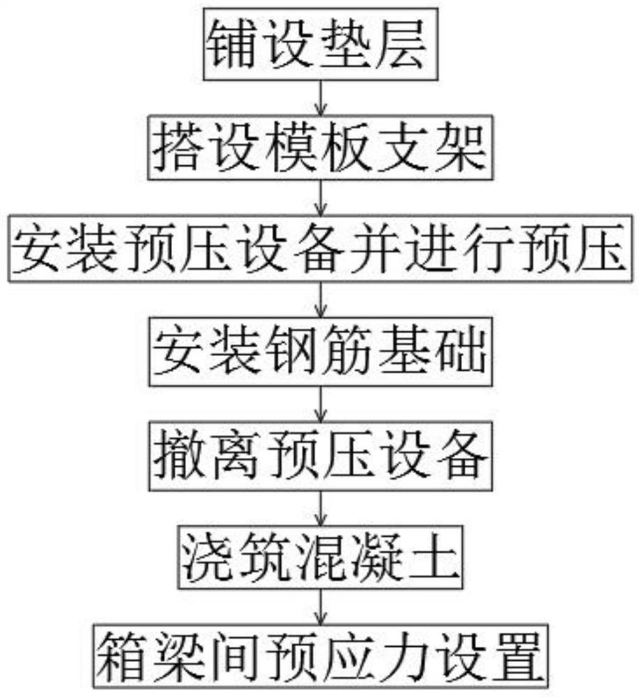
[0027] figure 1 , figure 2 and image 3 , the bridge construction method of cast-in-place box girder with full support includes the following steps:

[0028] Step 1: Lay the cushion, first clean and level the ground, and then pour 20cm of C20 plain concrete floor on the ground. The usefulness of laying the cushion mainly reflects the following points. First, it is mainly for fixing the formwork with expansion bolts The base of the bracket, secondly, when constructing the formwork support and preloading, avoid the settlement of the installation position of the formwork support;

[0029] Step 2: Set up the formwork support, put the wires on the floor to set up the formwork support. After the formwork support is set up, place the cross arm evenly on the formwork support. The ...


PUM


Abstract

The invention discloses a bridge construction method of a full framing cast-in-place box girder, which comprises the following steps: step 1, laying a cushion layer, step 2, erecting a template bracket, step 3, installing pre-pressing equipment and pre-pressing, and the pre-pressing equipment comprises track bed boards arranged on two sides of the template bracket, standard knots which are mutually fixed in the up-down and front-back directions are arranged on the track bed board in a sliding mode, the upper portions of the standard knots on the left side and the right side are mutually connected through a plurality of reinforcing frames, a fixing plate is arranged on the standard knot on the uppermost portion, the upper portion of the fixing plate is connected with a force bearing column, and a top plate is arranged on the top of the force bearing column. According to the construction method, an operator on each top plate only needs to operate a reversing valve of a hydraulic pump to realize stretching of a top rod of a hydraulic cylinder, so that a weight box pulled by a pulling rope is downwards pressed and upwards separated from the top of the template bracket, and the whole pre-pressing equipment can be pulled to the periphery of the next to-be-pre-pressed template bracket through a tractor; compared with the prior art that the pre-pressing blocks are hoisted to the formwork support one by one through a crane, pre-pressing construction is convenient.

Description

technical field [0001] The invention belongs to the technical field of bridge construction, and in particular relates to a bridge construction method for cast-in-place box girders with full support. Background technique [0002] The cast-in-place box girder of the full hall support is erected with dense formwork supports, and the box girder is cast in-situ. After the support is installed, hoist the pre-compression block to the pre-compression formwork support for pre-compression, measure the settlement of the formwork support, lift off the pre-compression block, measure the springback of the formwork support, and then install the prefabricated formwork on the formwork support, pour concrete, box After the concrete of the beam is solidified, the adjacent box girder is prestressed. During the whole process, because the supporting performance of the formwork support is extremely important, the inelastic deformation of the formwork support is eliminated by preloading, so as to e...

Claims


Application Information

Patent Timeline
IPC IPC(8): E01D21/00E01D2/04E01D101/24E01D101/28
CPCE01D21/00E01D2/04E01D2101/24E01D2101/28
Inventor 蒙书崔艳杰樊守福陈楠牛仁贵
Owner 蒙书
Features
  • R&D
  • Intellectual Property
  • Life Sciences
  • Materials
  • Tech Scout
  • Unparalleled Data Quality
  • Higher Quality Content
  • 60% Fewer Hallucinations
Learn More