Eureka AIR delivers breakthrough ideas for toughest innovation challenges, trusted by R&D personnel around the world.

Centrifugal pump capable of actively inhibiting cavitation as well as design method and mounting method of centrifugal pump

A technology of active suppression and centrifugal pumps, which is applied to parts, pumps, pump components, etc. of pumping devices for elastic fluids, and can solve the problems of limited bubble-like cavitation suppression effects, delayed cavitation, and limited suppression effects on the suction surface. problem, to achieve the effect of improving the effect of cavitation suppression and increasing the effect of connection

Pending Publication Date: 2022-03-22
ZHEJIANG HANYI ELECTROMECHANICAL CO LTD
View PDF0 Cites 0 Cited by
  • Summary
  • Abstract
  • Description
  • Claims
  • Application Information

AI Technical Summary

Problems solved by technology

[0003] For passive suppression methods, such as leading edge, blade tip modification, etc., their suppression effect on cavitation is very limited, and usually only can suppress a certain cavitation phenomenon, such as blade tip modification can delay the effect of tip vortex cavitation phenomenon occur, but the suppression effect on the suction surface bubble cavitation is very limited
The fundamental reason is that the local pressure can only be changed to a small extent by means of modifying the shape and adding bulges on the surface, delaying the occurrence of cavitation, but it cannot fundamentally solve the problem of the inlet, front edge, Low pressure problems on the suction side

Method used


Image

  • Centrifugal pump capable of actively inhibiting cavitation as well as design method and mounting method of centrifugal pump
  • Centrifugal pump capable of actively inhibiting cavitation as well as design method and mounting method of centrifugal pump
  • Centrifugal pump capable of actively inhibiting cavitation as well as design method and mounting method of centrifugal pump

Examples


Embodiment Construction

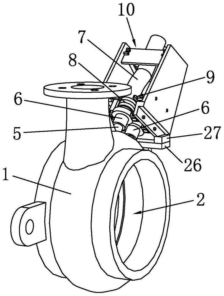
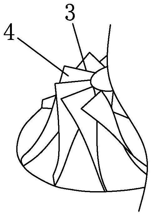
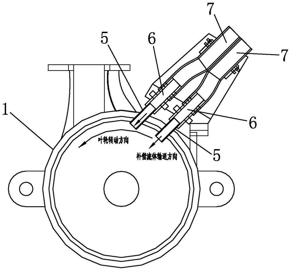
[0066] Such as Figure 1 to Figure 8 As shown, it is a centrifugal pump for actively suppressing cavitation according to the present invention, which includes a volute 1 and an impeller. A cavity 2 is provided inside the volute 1 , and the impeller is arranged in the cavity 2 . The present invention also includes a compensating pipe 5. The volute 1 is provided with a compensating hole. The compensating hole is correspondingly arranged at the low pressure area where the front edge 3 of the impeller and the suction surface 4 appear. The compensating tube 5 penetrates and is fixed in the compensating hole. The compensating tube 5 Send high-pressure compensation fluid to the low-pressure area, and the compensation fluid is sent along the rotation direction of the impeller. For example, when the impeller rotates counterclockwise, the compensation fluid is delivered at high pressure from right to left image 3 ). The present invention impacts the low-pressure area that occurs during ...


PUM


Abstract

The invention discloses a centrifugal pump capable of actively restraining cavitation and a design method and an installation method thereof, the centrifugal pump comprises a volute, an impeller and a compensation pipe, the volute is provided with compensation holes, the compensation holes are correspondingly formed in the front edge of the impeller and a low-pressure area where a suction surface appears, the compensation pipe penetrates into and is fixed in the compensation holes, and the compensation pipe conveys compensation fluid to the low-pressure area; the compensation fluid is conveyed along the rotating direction of the impeller; meanwhile, the centrifugal pump is specifically designed and installed for actively restraining cavitation. The low-pressure area appearing in the operation process of the centrifugal pump is impacted in the mode that the high-pressure compensation fluid is externally connected, so that generation and development of the cavitation phenomenon are delayed or restrained, compared with a passive restraining mode, the active restraining means can effectively restrain multiple cavitation modes, the cavitation restraining effect is improved, and the original hydraulic performance is basically not affected.

Description

technical field [0001] The invention belongs to the technical field of centrifugal pumps, in particular to a centrifugal pump for actively suppressing cavitation, its design method and its installation method. Background technique [0002] When the pressure of the liquid in the pump is less than its saturated vapor pressure, bubbles will form inside the liquid, and develop and collapse with the flow, which is cavitation. When the air bubble impacts the centrifugal pump blade and ruptures, it is accompanied by high temperature and high pressure, which causes the metal peeling on the surface of the centrifugal pump blade and reduces the life of the pump body. In addition, cavitation will also cause the centrifugal pump to work in abnormal environments such as vibration and noise. Therefore, when the centrifugal pump is in actual operation, the occurrence of cavitation should be avoided to the greatest extent. [0003] For passive suppression methods, such as leading edge, bl...

Claims


Application Information

Patent Timeline
IPC IPC(8): F04D29/66F04D29/42
CPCF04D29/669F04D29/426
Inventor 潘华杰
Owner ZHEJIANG HANYI ELECTROMECHANICAL CO LTD
Why Eureka
Eureka Blog
Learn More