Compact brake clamp unit shell

A brake caliper and unit housing technology, applied in the field of rail transit, can solve the problem that the vibration, impact and wear of rail vehicles and rail systems cannot be improved more effectively, which is detrimental to the braking reliability of the brake caliper unit of rail vehicles. Operational safety, restricting the stability of rail vehicles, reducing comfort and operating costs, etc., to achieve the effect of being conducive to effective transmission, improving eccentric wear, and eliminating adverse effects

Pending Publication Date: 2022-03-22
CRRC QISHUYAN INSTITUTE CO LTD +1
View PDF5 Cites 0 Cited by
  • Summary
  • Abstract
  • Description
  • Claims
  • Application Information

AI Technical Summary

Problems solved by technology

As a result, the manufacturing and assembly errors of the brake cylinder side cover directly affect the position accuracy of the hinge point of the push rod assembly 3 relative to the housing, which in turn affects the motion accuracy of the push rod, resulting in a gap required in the actual braking process of the rail vehicle. The adjustment amount cannot be transmitted accurately and reliably, which is not conducive to the braking reliability of the brake caliper unit and the safety of rail vehicle operation, and is also inconvenient for daily inspection and maintenance
[0006] In addition, the mass of the existing compact brake caliper unit is close to 100kg, which increases the unsprung mass burden of the rail vehicle and the force of the wheel and rail, and the vibration, impact and wear between the rail vehicle and the rail system cannot be obtained more effectively. The improvement of rail vehicles seriously restricts the running stability, comfort and reduction of operating costs of rail vehicles

Method used


Image

  • Compact brake clamp unit shell
  • Compact brake clamp unit shell
  • Compact brake clamp unit shell

Examples


Embodiment 1

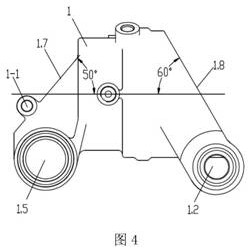
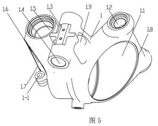
[0030] The compact brake caliper unit housing 1 of the present embodiment is as Figure 4 and Figure 5 As shown, there is an installation hole 1.1 of the brake cylinder piston assembly 2, a push rod assembly cavity 1.6 communicating with one end of the installation hole 1.1, a transmission mechanism assembly hole 1.5, a lever pin assembly hole 1.2, and a horizontal suspension assembly hole 1.4. The axis of the mounting hole 1.1 is coaxial with the piston of the brake cylinder piston assembly 2, and the mounting hole 1.1 provides a relatively sufficient space for the brake cylinder piston assembly 2 to move laterally in the housing, and the movement of the piston is smoother. The axes of the mounting holes 1.1 are generally arranged along the transverse direction. The axes of the transmission mechanism assembly hole 1.5 and the lever pivot assembly hole 1.2 are respectively arranged vertically, and the axes of the horizontal suspension assembly hole 1.4 are arranged roughly a...


PUM


Abstract

The invention relates to a compact brake clamp unit shell, and belongs to the technical field of rail transit. The shell is provided with a brake cylinder piston assembly mounting hole and a push rod assembly cavity communicated with one end of the mounting hole; the outer end of the push rod assembly cavity is a side cover mounting surface inclined to the axis of the mounting hole; one end, far away from the push rod assembly cavity, of the mounting hole is an end cover mounting surface; and one end of the side cover mounting surface is provided with a push rod assembly hinging structure. With the adoption of the invention, the positioning and movement precision of the push rod assembly can be fully ensured, and the adverse effect on the positioning and movement precision of the push rod assembly caused by vibration or looseness of fastening connection between the shell and the brake cylinder side cover is avoided; accurate and stable transmission of the required clearance adjustment amount during clamp braking is effectively guaranteed, and then the braking reliability and the operation safety are guaranteed. And the brake cylinder side cover can be conveniently disassembled, so that the action condition of each part in the shell can be conveniently checked, and great convenience is brought to detection and maintenance.

Description

technical field [0001] The invention relates to a brake caliper unit housing, in particular to a compact brake caliper unit housing, which belongs to the technical field of rail transportation. Background technique [0002] The compact brake caliper unit (referred to as the caliper unit) is usually installed under the rail vehicle bogie, and its typical structure can be found in Chinese patent documents with application numbers 201120029779.1, 201220106387.5, and 201210075036.7. When the rail vehicle brakes due to deceleration or parking, if the gap between the brake disc and the brake pad exceeds the predetermined gap range, the clamp unit will The movement of the push rod assembly between them transmits the amount of clearance adjustment required for caliper braking. For the specific working principle of the gap adjustment, please refer to the Chinese patent documents with the announcement numbers CN104260748A and CN207795925U. [0003] The housing as the key part of the...

Claims


Application Information

Patent Timeline
Patent Type & Authority Applications(China)
IPC IPC(8): F16D65/00B61H5/00
CPCF16D65/00B61H5/00
Inventor 苟青炳张萍兴百宪李娄明梅卓民何一帆
Owner CRRC QISHUYAN INSTITUTE CO LTD
Why Eureka
Try Eureka