Earthwork backfilling elevation measuring device suitable for large-size foundation pit or trench

An elevation measurement and large-scale technology, applied in the direction of measuring devices, optical devices, instruments, etc., can solve the problems of unsatisfactory measurement, inaccurate measurement results, interference of measurement accuracy, etc., and achieve strong practicability and market competitiveness. Structure The effect of simple design and guaranteed accuracy

Pending Publication Date: 2022-03-22
CHINA RAILWAY CONSTR ENG GROUP +1
View PDF0 Cites 2 Cited by
  • Summary
  • Abstract
  • Description
  • Claims
  • Application Information

AI Technical Summary

Problems solved by technology

The elevation of backfill soil is obtained by subtracting the height of the road structure after subtracting the height of the project bottom from the height of the road. Therefore, the measurement of the bottom height of the project is the basis for determining the elevation of the backfill soil. In the existing construction process, engineering personnel generally It is to manually measure the elevation of earthwork backfilling for the subject matter that needs to be backfilled, such as the road surface and foundation pit. The process is cumbersome, and the measurement accuracy of this method is easily affected by human factors. Higher construction demand
[0003] In order to solve the above problems, those skilled in the art have designed a device for automatically measuring the elevation. This device is generally installed at the opening of the foundation pit or trench, and measures the elevation of the earthwork backfill by means of optical ranging, thereby solving the problem of manual measurement. The process is cumbersome, and the measurement accuracy is easily disturbed by factors; however, when the excavated trenches for foundation pits or pavement construction are too large, the existing automatic measuring devices are difficult to fix and cannot meet the needs of large foundation pits. Or the measurement of the earthwork backfill elevation of a large trench

Method used


Image

  • Earthwork backfilling elevation measuring device suitable for large-size foundation pit or trench
  • Earthwork backfilling elevation measuring device suitable for large-size foundation pit or trench

Examples


Embodiment Construction

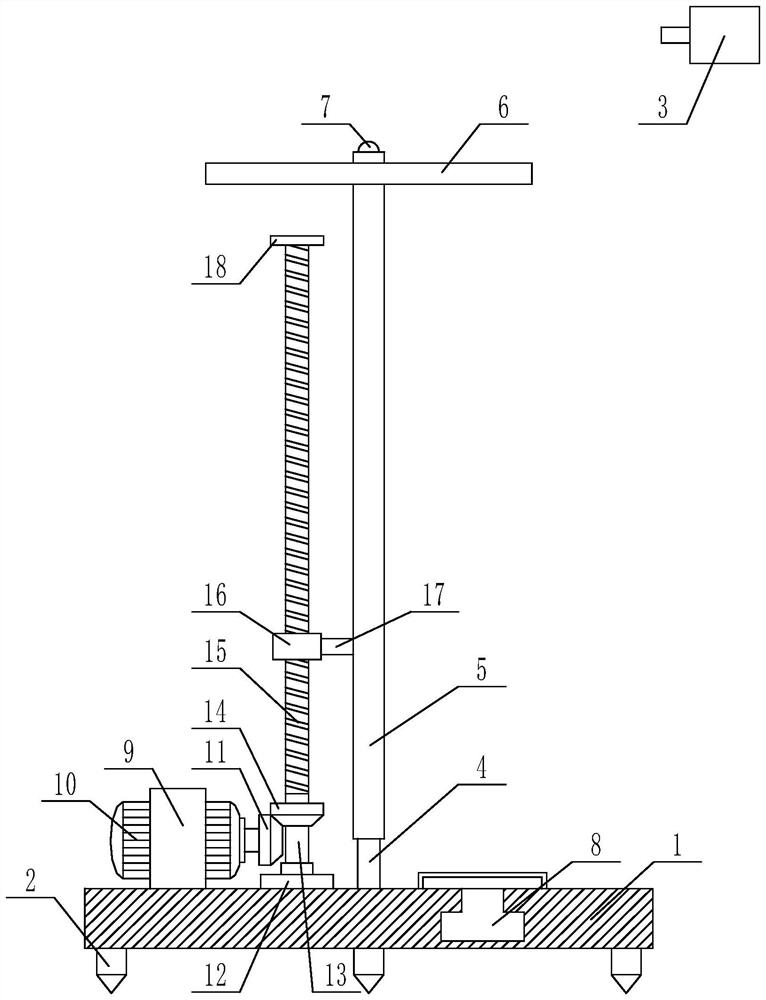
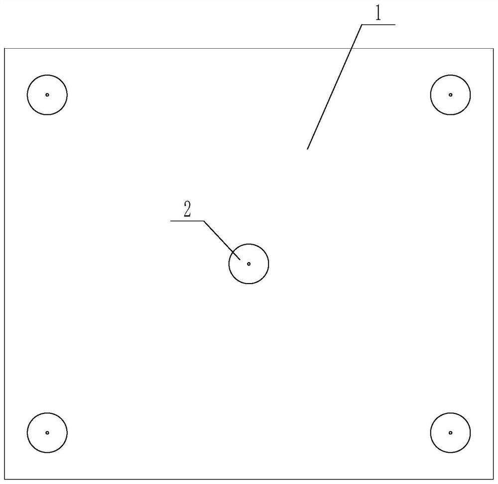
[0025] The present invention is specifically described below in conjunction with accompanying drawing, as Figure 1-2 shown;

[0026] The invention of the present application is that the upper surface of the base is fixed with a column 4, the column is perpendicular to the upper surface of the base and the column is located at the center of the upper surface of the base, the column is covered with a sleeve 5, the A top plate 6 is fixedly installed on the casing, the column is perpendicular to the top plate, the top plate is close to the top of the column, and a photosensitive sensor 7 is fixedly installed on the upper end surface of the column, and the photosensitive sensor sends a signal to the control terminal through a wire;

[0027] The invention of the present application is also that the distance measuring sensor 8 is fixedly installed on the upper surface of the base, the distance measuring sensor is connected with the mobile terminal through the wireless communication ...


PUM


Abstract

The invention discloses an earthwork backfill elevation measuring device suitable for a large-size foundation pit or trench, which comprises a base, a plurality of fixing cones arranged on the lower surface of the base, and a laser indicator, an upright column is fixedly mounted on the upper surface of the base, a sleeve is sleeved on the upright column, a top plate is fixedly mounted on the sleeve, and the laser indicator is fixedly mounted on the top plate. A photosensitive sensor is fixedly installed on the upper end face of the stand column, a distance measuring sensor is fixedly installed on the upper surface of the base, a stepping motor is fixedly installed on the upper surface of the base, a first bevel gear is fixedly installed on a rotating shaft of the stepping motor, and a second bevel gear is fixedly installed on a transmission shaft. The first bevel gear is meshed with the second bevel gear, the upper end of the transmission shaft is fixedly connected with a lead screw, a nut seat is installed on the lead screw, and the side surface of the nut seat is fixedly connected with the side surface of a sleeve through a connecting rod. The method has the beneficial effects that the method is suitable for a measurement environment with a larger foundation pit or groove, and the measurement process is simple and practical.

Description

technical field [0001] The invention relates to the technical field of building construction, in particular to an earthwork backfill elevation measuring device suitable for large-scale foundation pits or trenches. Background technique [0002] Backfilling soil refers to the soil that is returned for filling after the foundation and other underground works are completed during engineering construction. In order to ensure that there will be no problems such as settlement cracks after backfilling construction, engineers must accurately grasp the elevation of backfilling before backfilling, so as to accurately calculate the amount of backfilling of earthwork, and avoid unevenness of the bottom surface caused by too much or too little earthwork The problem. The elevation of backfill soil is obtained by subtracting the height of the road structure after subtracting the height of the project bottom from the height of the road. Therefore, the measurement of the bottom height of the...

Claims


Application Information

Patent Timeline
Patent Type & Authority Applications(China)
IPC IPC(8): G01B11/02
CPCG01B11/02
Inventor 梁荣财王文立王虹程罗明于宁飞尚书礼展昆昆孙聪杨建吴彬韩勇成张因寒丁鹏伟杨英琪许鹏
Owner CHINA RAILWAY CONSTR ENG GROUP
Why Eureka
Try Eureka