
Intelligent supervision and testing equipment for fire emergency lights

A technology for fire emergency and detection equipment, applied in program control, instrumentation, computer control, etc., can solve the problems of insufficient detection time, low degree of automation, and high difficulty, to eliminate the influence of external lighting conditions, improve detection efficiency, and automate high degree of effect

Active Publication Date: 2022-07-15
山东钰涛消防科技有限公司
View PDF7 Cites 0 Cited by
  • Summary
  • Abstract
  • Description
  • Claims
  • Application Information

AI Technical Summary

Problems solved by technology

[0004] However, the existing detection equipment and detection methods often cover the lamps or self-generating light storage indicator stickers with a shading cover, place the lamps or indicator stickers to be tested in a dark environment, and after a period of time, perform illuminance or brightness detection to complete the attenuation discharge. Test, according to the detected data parameters to judge whether the fire emergency lights or self-generating light-storage indicator stickers are qualified products, so as to meet the actual use needs; because the existing hood is manually placed by the staff, to achieve a completely closed dark The environment is difficult. During the detection process, there will be external light penetrating in, and the detection data has large errors, which cannot accurately reflect the use status of the lamps or indicator stickers. At the same time, the setting of the detection time is not convenient enough. Various functional components in the system lack coordination and linkage, and the degree of automation is low, which is not conducive to promotion and use in different application scenarios

Method used


Image

  • Intelligent supervision and testing equipment for fire emergency lights
  • Intelligent supervision and testing equipment for fire emergency lights
  • Intelligent supervision and testing equipment for fire emergency lights

Examples


Embodiment Construction

[0036] In order to clearly illustrate the technical features of the solution, the present invention will be described in detail below through specific embodiments and in conjunction with the accompanying drawings.

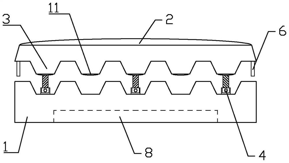
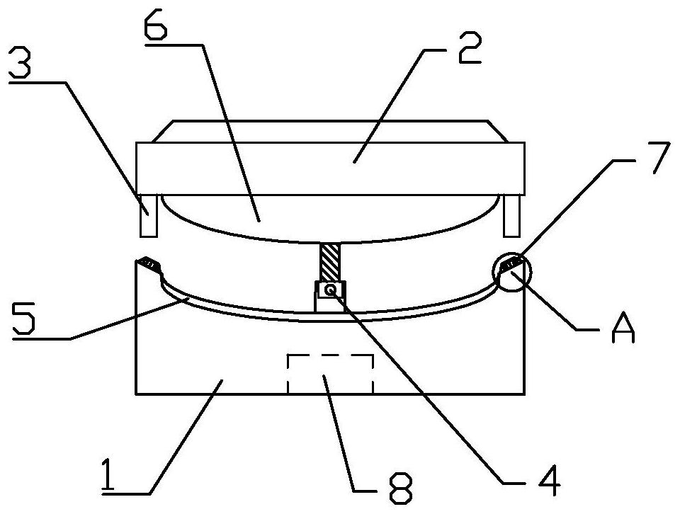
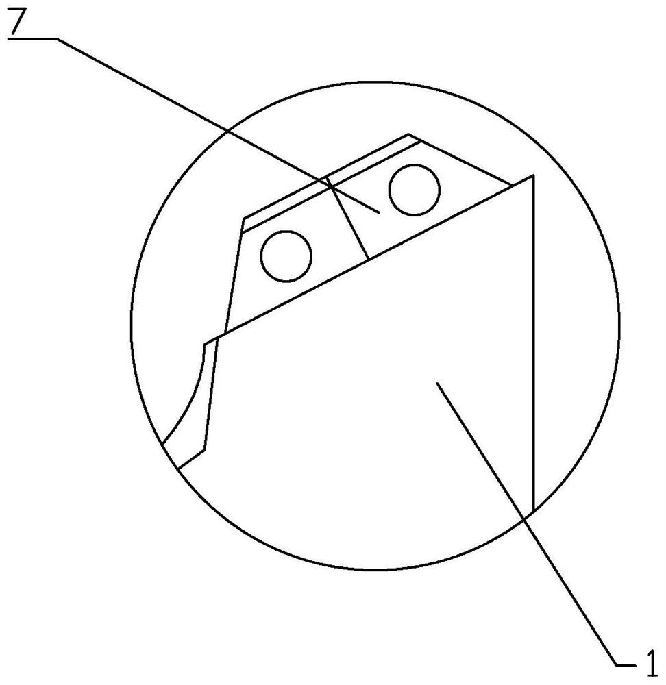
[0037] like Figure 1-17As shown in the figure, the intelligent supervision and detection equipment for fire emergency lights includes a base body 1 and a sealing buckle cover 2, and a plurality of closing teeth 3 are arranged at equal intervals on both sides of the base body 1 and the bottom sides of the sealing buckle cover 2 respectively. The teeth 3 are engaged to form a dark sealing detection space between the base body 1 and the sealing buckle cover 2; the base body 1 is connected with the sealing buckle cover 2 through a plurality of linear push rods 4, and the linear push rods 4 are used to drive the sealing The buckle cover 2 is lifted up and down; the two ends of the base body 1 are respectively provided with limit grooves 5 , and the two ends of the seal...


PUM


Abstract

The intelligent supervision and detection equipment for fire emergency lights includes a base body and a sealing buckle cover. A plurality of closing teeth are arranged at equal intervals on both sides of the base body and on both sides of the bottom of the sealing buckle cover. A dark sealing detection space is formed between the buckle covers; the base body is connected with the sealing buckle cover through a plurality of linear push rods, and the linear push rods are used to drive the sealing buckle cover to rise and fall; The two ends of the sealing buckle cover are respectively provided with limit arcs matched with the limit slots; proximity switches are respectively inclined on the bases on both sides of the limit slots, and the proximity switches are used to detect the position parameters of the limit arcs; A multi-deformation through hole is arranged at the bottom of the base body, and the through hole is used to place a fire emergency lamp to be detected or a self-generated light storage indicator sticker; a controller is arranged in the base body, and the controller is connected with a temperature through an AD converter. Sensors and Light Meters.

Description

Technical field: [0001] The invention relates to intelligent supervision and detection equipment for fire emergency lights. Background technique: [0002] Fire emergency light is suitable for fire emergency lighting and is the most common lighting tool in fire emergency. It has a long emergency time, high brightness and has automatic emergency emergency function when power off; Hotels, schools, units and other public places are used for emergency lighting in case of power failure, with low power consumption and long service life. [0003] Under normal circumstances, fire emergency lights are divided into two installation methods: wall-mounted and hanging; in practical application scenarios, fire emergency lights are often set and used in conjunction with self-generated light storage indicator stickers; after a period of use, it is necessary to adjust the lamps and lanterns and The indicator sticker is subjected to a discharge test to detect the brightness or illuminance of ...

Claims


Application Information

Patent Timeline
Patent Type & Authority Patents(China)
IPC IPC(8): G05B19/042
CPCG05B19/0423G05B2219/24215
Inventor 王继艳张国栋
Owner 山东钰涛消防科技有限公司
Learn More