Forward-looking sonar beam domain image splicing method

A forward-looking sonar and image stitching technology, which is applied in image enhancement, image analysis, image data processing, etc., can solve the problems of increased stitching complexity and time-consuming calculation, weakening or even replacement of real point values, and edge gray value jumps and other problems to achieve the effect of eliminating the problem of splicing seams and false target values, eliminating the problem of false target values, and improving efficiency

Pending Publication Date: 2022-03-22
HARBIN ENG UNIV
View PDF0 Cites 0 Cited by
  • Summary
  • Abstract
  • Description
  • Claims
  • Application Information

AI Technical Summary

Problems solved by technology

The fan-shaped outer edge interpolation calculation lacks enough neighboring points to participate, resulting in obvious jumps in the edge gray value of the interpolated edge, which needs to be eliminated by adding templates during splicing, otherwise obvious fan-shaped edges will be left, which increases the splicing. Complexity and calculation time-consuming; for fan-shaped images in the image domain, the gray value of the interpolation point is approximately calculated, and the fusion of the interpolation point value and the rea

Method used


Image

  • Forward-looking sonar beam domain image splicing method
  • Forward-looking sonar beam domain image splicing method
  • Forward-looking sonar beam domain image splicing method

Examples


Embodiment Construction

[0048] The present invention will be further described below in conjunction with the accompanying drawings and embodiments of the description.

[0049] The present invention comprises the following steps:

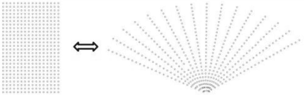
[0050] 1. The forward-looking sonar image data is collected and stored in the beam domain in the form of a two-dimensional image. The horizontal axis of the image represents the number N of sonar beams, and the vertical axis represents the number M of sampling points of each beam;

[0051] 2. According to the forward-looking sonar parameters, including the number of beams N, the number of sampling points for each beam M and the unit horizontal opening angle θ 0 Construct the expression domain mapping constellation diagram to form the corresponding relationship between the coordinates of the sampling points in the beam domain and the coordinates in the image domain;

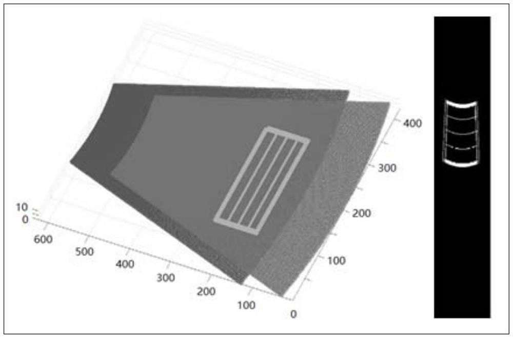
[0052] 3. According to the expression domain mapping constellation diagram, split the actual motion mode of...


PUM


Abstract

The invention discloses a foresight sonar beam domain image splicing method, which comprises the following steps of: constructing an expression domain mapping constellation diagram, and forming a data conversion relationship between a beam domain and an image domain; according to an expression domain mapping constellation diagram, splitting actual sonar motion, and constructing an expression domain mapping model in a rotation motion mode and a displacement motion mode; the method comprises the following steps of: adopting an actually measured near-frame sonar image, decomposing the actual sonar motion condition according to rotation motion and displacement motion by taking a previous frame image as a benchmark, and performing image deformation operation on a next frame image by referring to an expression domain mapping model to realize target superposition in the two images; carrying out image fusion on the two beam domain images of which the targets are overlapped by adopting a Laplace pyramid hierarchical fusion strategy; a forward-looking sonar sequence image is adopted, continuous multi-frame data beam domain splicing operation is carried out, and the image is expanded to an image domain through interpolation. According to the method, edge seams generated in the image and splicing are well removed, and a false target value occurring in the fan-shaped expansion interpolation operation splicing process is eliminated.

Description

technical field [0001] The invention belongs to digital image processing technology, and relates to a forward-looking sonar beam domain image mosaic method, in particular to a forward-looking sonar beam domain image mosaic method based on an expression domain mapping model. Background technique [0002] Image stitching is the process of combining images with overlapping regions from different perspectives of the same scene to form a wide-field, information-rich image. Image stitching plays a vital role in digital image processing and has become a popular field in photogrammetry, computer vision, image processing and computer graphics, and is widely used in remote sensing, aerospace, virtual reality, medical imaging, 3D reconstruction and other fields. [0003] The existing mosaic method of forward-looking sonar images is mainly carried out with reference to the method of optical image mosaic, and the content of the two images to be mosaic is completed by feature extraction ...

Claims


Application Information

Patent Timeline
IPC IPC(8): G06T3/40G06T5/50
CPCG06T3/4038G06T5/50G06T2207/10132G06T2207/20016G06T2207/20221
Inventor 卞红雨魏明哲吕征张锋林存毅
Owner HARBIN ENG UNIV
Why Eureka
Try Eureka