
Distributed attenuator suitable for folded waveguide traveling wave tube and distributed attenuation method

A technology of distributed attenuation and folded waveguide, applied in traveling wave tubes, circuit components of transit time electron tubes, etc., can solve the problems of complex process, poor consistency, large reflection coefficient, etc., achieve simple process, reduce cost, improve performance effect

Pending Publication Date: 2022-03-22
NO 12 RES INST OF CETC
View PDF0 Cites 0 Cited by
  • Summary
  • Abstract
  • Description
  • Claims
  • Application Information

AI Technical Summary

Problems solved by technology

[0006] An object of the present invention is to provide a distributed attenuation method and a distributed attenuator suitable for folded waveguide traveling wave tubes, in order to effectively prevent the self-excited oscillation of the traveling wave tube while improving performance indicators such as gain fluctuations, and the process Simple, good consistency, solve the problems of large reflection coefficient, complex process, poor consistency and other problems in the traditional coating attenuation coating method

Method used


Image

  • Distributed attenuator suitable for folded waveguide traveling wave tube and distributed attenuation method
  • Distributed attenuator suitable for folded waveguide traveling wave tube and distributed attenuation method
  • Distributed attenuator suitable for folded waveguide traveling wave tube and distributed attenuation method

Examples


Embodiment

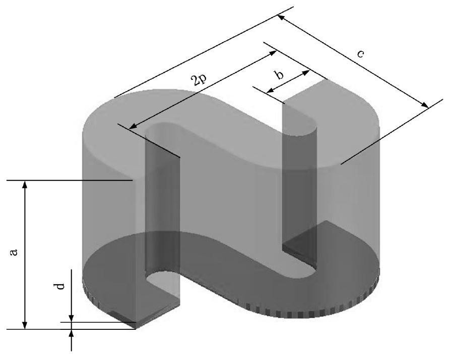
[0041] The distributed attenuator applicable to the folded waveguide provided in the embodiment is as image 3 and Figure 4 As shown, the cavity length Lt is 3 times the folded waveguide geometric period 2p length (2p=1.2mm), Lt=3.6mm; depth at=2.3mm; width bt=0.2mm; the cavity communicates with the curved waveguide connecting section Depth dt=0.08mm; S1=3.22mm, S2=2.62mm. The attenuating ceramic material in the distributed attenuator is aluminum nitride.


PUM


Abstract

The invention discloses a distributed attenuation method and a distributed attenuator suitable for a folded waveguide traveling wave tube, electromagnetic waves propagating in a folded waveguide are properly attenuated through a ceramic attenuation body having certain coupling with a folded waveguide slow wave system, and the ceramic attenuation body is the distributed attenuator and is in the shape of a cuboid. By reasonably selecting the size parameters of the distributed attenuator, the type of the ceramic material and the communication degree of the distributed attenuator and the folded waveguide, the attenuation amount of the electromagnetic wave can be controlled within a required range. The method has the advantages of being simple in process, good in consistency, controllable in attenuation amount and the like, the gain fluctuation of the folded waveguide traveling wave tube can be effectively improved, and the performance of the traveling wave tube is improved.

Description

technical field [0001] The invention relates to the technical field of microwave vacuum electronics. More specifically, it relates to a distributed attenuator and a distributed attenuation method suitable for folded waveguide traveling wave tubes. Background technique [0002] The traveling wave tube is a wide-band high-gain device. The reflection in the tube will cause the gain fluctuation of the traveling wave tube to increase, the performance will deteriorate, and even cause self-excited oscillation in severe cases, so that the traveling wave tube cannot work normally. The reflection in the tube cannot be completely eliminated, and the concentrated attenuator and the energy coupling port are usually the main parts causing the reflection. Generally, the method of increasing the line loss is used to attenuate the reflected signal, so as to avoid the self-excited oscillation of the traveling wave tube and improve the gain fluctuation of the traveling wave tube. Specificall...

Claims


Application Information

Patent Timeline
Patent Type & Authority Applications(China)
IPC IPC(8): H01J25/34H01J23/30
CPCH01J25/34H01J23/30
Inventor 字张雄陈炤飞刘世硕谢青梅吴玉娟
Owner NO 12 RES INST OF CETC
Learn More