Display panel side surface terminal printing system

A printing system and display panel technology, applied in printing, printing machines, transfer printing, etc., can solve problems such as inability to form various patterns, and achieve the effect of preventing unqualified printing

Pending Publication Date: 2022-03-22
PS IND CO LTD
View PDF13 Cites 0 Cited by
  • Summary
  • Abstract
  • Description
  • Claims
  • Application Information

AI Technical Summary

Problems solved by technology

[0008] However, the prior art document has a limitation that various patterns cannot be formed because the terminal is formed using only the side surface of the display panel, so the formed pattern is a terminal with a two-dimensional pattern.

Method used


Image

  • Display panel side surface terminal printing system
  • Display panel side surface terminal printing system
  • Display panel side surface terminal printing system

Examples


Embodiment Construction

[0052] Examples of the display panel side terminal printing system according to the present invention can be applied in various embodiments, and the most preferred embodiments will be described below with reference to the accompanying drawings.

[0053] First of all, when the present invention will be described below, it will be described around the case where the present invention is applied to the rotary movement type in the above-mentioned prior art as an example. Therefore, even if it is not mentioned below, it should be understood that the technical characteristics of the present invention are also It can be applied to the plane mobile type in the prior art.

[0054] Based on this, in the present invention, those configurations that are not described in detail can be understood with reference to the prior art.

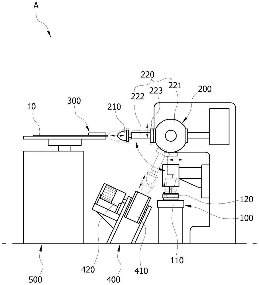
[0055] figure 1 It is a configuration diagram of an embodiment of the display panel side terminal printing system according to the present invention.

[0056] r...


PUM


Abstract

The present invention relates to a display panel side surface terminal printing system, and more specifically, when a terminal is formed on the side surface of a thin display panel, a pad printing method is adopted, so that the side surface terminal can be quickly and accurately formed. In particular, the present invention easily forms a three-dimensional strip-shaped pattern of a shape ("-shaped cross-section) extending from a side surface to an upper surface (or a front surface) and a lower surface (or a rear surface) with respect to the side surface of one side edge of a display panel. Accordingly, when the display panel with a large area is manufactured and display panels with various shapes are manufactured, a quite large free space can be provided in the designing and manufacturing process. Therefore, the present invention can improve credibility and competitiveness not only in the field of display panels, the field of display panel manufacturing, and the field of devices and systems for manufacturing display panels, but also in the similar or associated fields.

Description

technical field [0001] The invention relates to a side terminal printing system of a display panel. More specifically, when forming a terminal on the side of a thin display panel, a pad printing method (PAD printing type) is adopted, so that the side terminal can be formed quickly and accurately. [0002] In particular, the present invention relates to a display panel side terminal printing system that can easily form a shape extending from the side to the upper (or front) and lower (or rear) sides with reference to the side of one side edge of the display panel (" ” type cross-section) of the three-dimensional bar pattern. Background technique [0003] The flat panel display device capable of displaying images can be exemplified: a liquid crystal display (LCD, Liquid Crystal Display), a light emitting diode (LED, Light Emitting Diode) display, a micro light emitting diode (LED, Light Emitting Diode) display, a plasma display panel (PDP, Plasma Display Panel), Field Emissi...

Claims


Application Information

Patent Timeline
Patent Type & Authority Applications(China)
IPC IPC(8): B41F17/24B41F17/00B41F16/00
CPCB41F17/001B41F17/14B41F16/006B41P2217/60
Inventor 徐荣锡
Owner PS IND CO LTD
Why Eureka
Try Eureka