
Multifunctional virtual electronic instrument

An electronic instrument and multi-functional technology, which is applied in the field of multi-functional virtual electronic instruments, can solve problems such as unskilledness, and achieve the effects of easy portability, improved autonomy and hands-on ability, and low price

Pending Publication Date: 2017-06-30
NORTHEAST NORMAL UNIVERSITY
View PDF4 Cites 5 Cited by
  • Summary
  • Abstract
  • Description
  • Claims
  • Application Information

AI Technical Summary

Problems solved by technology

However, due to the limitations of the laboratory itself and class hours, students are not proficient in using some commonly used electronic measuring instruments in the laboratory, such as signal generators, oscilloscopes, multimeters, etc., which requires the introduction of new experimental methods in physical experiments. , establish a new teaching model

Method used


Image

  • Multifunctional virtual electronic instrument
  • Multifunctional virtual electronic instrument
  • Multifunctional virtual electronic instrument

Examples


Embodiment 1

[0039] The use of embodiment 1 signal generator

[0040] (1) The operator first opens the upper computer program on the computer side, and turns on the main switch of the upper computer; (2) connects the lower computer to the computer through the USB cable, and turns on the power switch of the lower computer, and waits for the power indicator to light; (3) Select the instrument function in the host computer interface, turn the function selection switch to the position of the signal generator, and the host computer automatically enters the signal generator interface; (4) set the signal waveform, frequency, amplitude, phase, DC bias voltage and select the channel to generate the signal, and then click the setting button on the signal generator interface; (5) Use the A output or B output of the signal generator according to the selected channel (6) If you need to repeat the experiment, repeat the operation Steps (4) to (6) are sufficient; (7) After the operation is completed, tur...

Embodiment 2

[0041] The use of embodiment 2 frequency characteristic instrument

[0042] (1) The operator first opens the upper computer program on the computer side, and turns on the main switch of the upper computer; (2) connects the lower computer to the computer through the USB cable, and turns on the power switch of the lower computer, and waits for the power indicator to light; (3) Select the instrument function in the interface of the upper computer, and turn the function selection switch to the position of the frequency characteristic meter, and the upper computer automatically enters the interface of the frequency characteristic meter; (4) Set the starting frequency, cut-off frequency, amplitude value, frequency step value, and set the horizontal and vertical coordinate range of the semi-logarithmic graph, and then click the setting button on the interface of the frequency characteristic instrument; (5) Connect the A pin of the output terminal A of the signal generator that generat...


PUM


Abstract

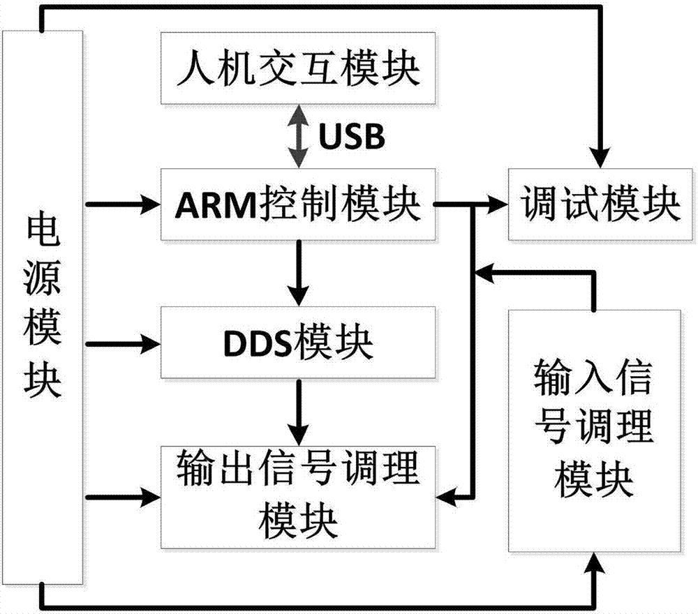
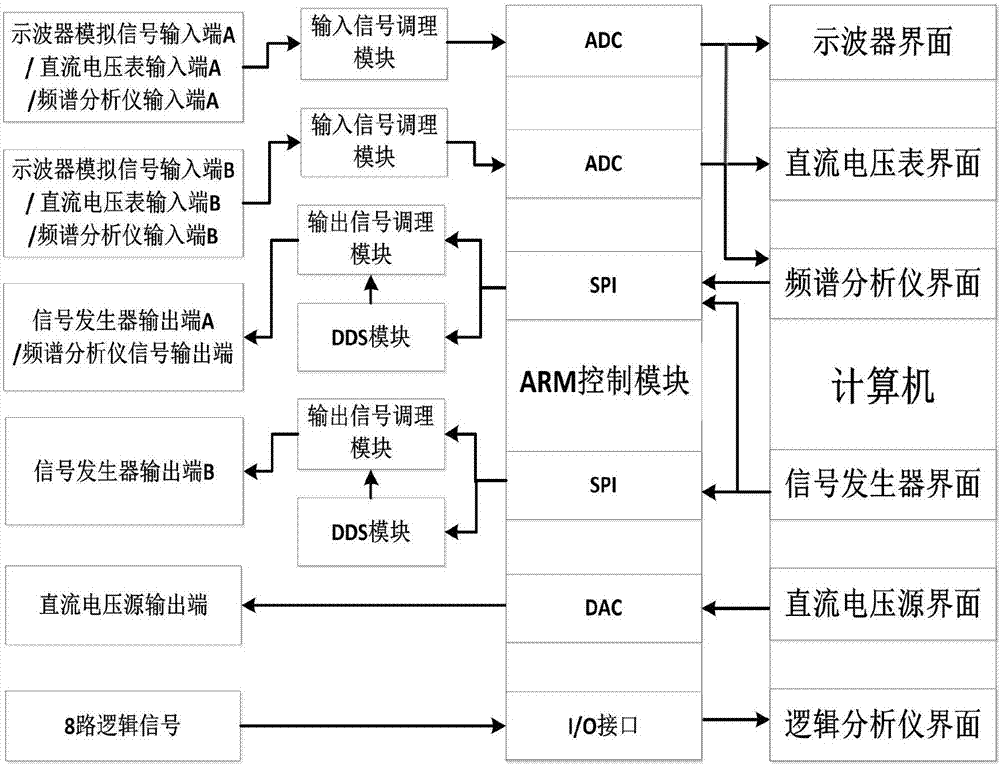
The invention discloses a multifunctional virtual electronic instrument, which comprises the functions of a digital oscilloscope, a signal generator, a DC voltage source, a DC voltmeter, a frequency characteristic analyzer and a logic analyzer. The multifunctional virtual electronic instrument comprises a human-machine interaction module, an ARM control module, an input signal regulating module, a DDS module, an output signal regulating module, a power supply module, and a debugging module. According to the instrument of the invention, the strong data processing ability of a computer is utilized; the hardware circuit size is reduced; the consumed material cost is reduced; the circuits are more integrated; and therefore, the instrument becomes portable to carry and convenient to use. The instrument further overcomes the limitation that a traditional electronic testing instrument can only be used in laboratories. Therefore, the students could use it for testing at any time and any place. The students are entitled to the largest freedom to do so, and a completely open laboratory in true sense comes into being.

Description

technical field [0001] The invention relates to the field of electronic measurement, in particular to a multifunctional virtual electronic instrument. Background technique [0002] With the rapid development of computer technology, integrated circuit technology and electronic measurement technology, electronic measuring instruments have been widely used in scientific research, experimental teaching and industrial production. Due to the high cost, low integration, bulky size, and inconvenient portability of traditional electronic measuring instruments, their further development and application are hindered. A solution is urgently needed to improve the shortcomings of existing electronic instruments. [0003] Compared with traditional instruments, the main advantages of virtual instruments lie in the flexibility and powerful functions of applications. In a virtual instrument, hardware is used only for signal input and output. This not only reduces the use of components, save...

Claims


Application Information

Patent Timeline
Patent Type & Authority Applications(China)
IPC IPC(8): G09B23/18
CPCG09B23/182G09B23/185
Inventor 赵振宇王连明陈菊芳
Owner NORTHEAST NORMAL UNIVERSITY
Learn More