Foam maker

A bubbler and foam technology, which is used in brackets or dispensers, household appliances, sanitary equipment, etc., can solve the problem of difficulty in effectively stirring mixed liquid, foaming results that are easy to vary from person to person, and inability to effectively generate foam blocks, etc. question

Active Publication Date: 2015-11-11
MAXELL HLDG LTD
View PDF6 Cites 6 Cited by
  • Summary
  • Abstract
  • Description
  • Claims
  • Application Information

AI Technical Summary

Problems solved by technology

However, since the mixture of water and solution (foaming element) is stirred with a brush held by one hand, the foaming result is likely to vary from person to person, and it is difficult to make a sufficient amount of finer foam well by the user's technique. Bubble
In addition, since the large-diameter protrusions and small-diameter protrusions are only formed on the lower half of the inner surface of the container body, the mixed liq

Method used


Image

  • Foam maker
  • Foam maker
  • Foam maker

Examples


Embodiment 1

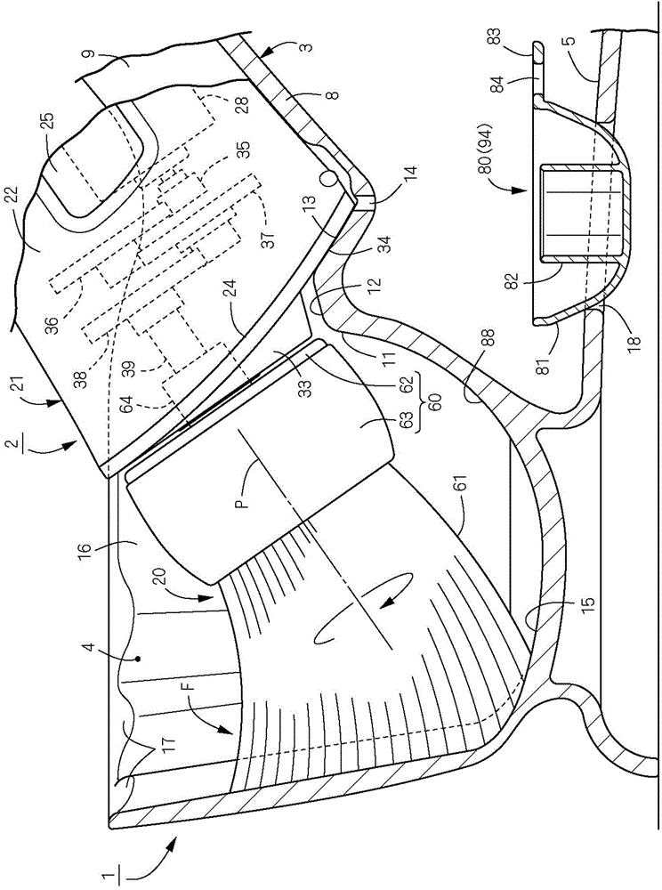
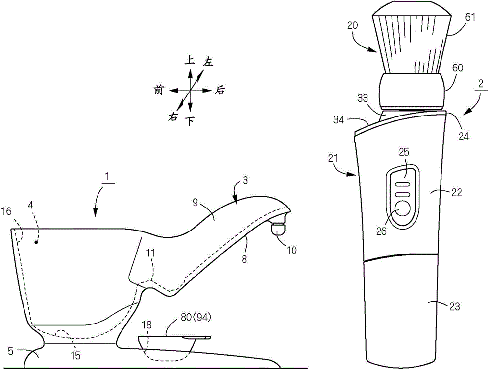
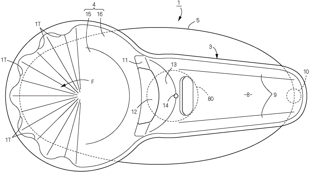
[0142] (Example 1) Figure 1 to Figure 15 Shown is the bubbler of Example 1 of the present invention. Front and rear, left and right, and up and down in the present invention are in accordance with figure 2 as well as Figure 5 The cross arrows and the front and rear, left and right, and up and down displays marked near the cross arrows. figure 2 Among them, the bubbler is composed of a foaming container 1, a stirring body 2 attached to the foaming container 1, and a stand 3 for supporting the stirring body 2 in a stirring posture. The foaming container 1 is composed of a currypot-shaped plastic molded product, and is integrally provided with a foam generating part 4 that is circular in plan view and opens upward, a pedestal 5 supporting the foam generating part 4, and a foam generating part that is connected to the foam generating part. The bracket 3 is continuously formed at the rear upper part of the part 4.

[0143] The bracket 3 is formed in a U-shaped trough in cro...

Embodiment 2

[0177] (Example 2) Figure 16The brush body 20 of Example 2 which changed the brush structure is shown. Here, the brush shaft portion 76 of the brush bundle 61 is formed in an inverted truncated cone shape similarly to the brush body of Embodiment 1, but the difference is that the entire brush tip is formed with a partially spherical concave surface to form a holding recess 78 . The brush front end portion 77 in this case is an arc edge of the upper end of the brush shaft portion 76 . As mentioned above, if the volume of the holding recess 78 is set larger, the amount of foaming agent or foaming elements retained in the holding recess 78 can be changed in a variety of ways, so it is possible to respond to the foaming agent or foam The manufacturer of the element is different, and the foaming characteristics are different. And, when foaming, the brush front end portion 77 is elastically deformed, and collides with the foaming rib 17 while swinging in a state in which the foam...

Embodiment 3

[0178] (Example 3) Figure 17 The foaming container 1 of Example 3 which changed the container structure of the foam generating part 4 is shown. Here, the foam return wall 88 and the bottom wall 15 of the foam generating part 4 are formed in a smoothly curved concave shape, and the entire bottom wall 15 including the foam return wall 88 is inclined downward toward the foaming part F. The degree of inclination of the foam return wall 88 is substantially the same as the degree of inclination of the rotation center axis P of the brush body 20 . According to such a foam generating part 4, the foam block flowing toward the foam return wall 88 side and the foam block intended to stay on the bottom wall 15 of the device can be reliably flowed toward the foaming part F, and can be repeatedly stirred by the brush bundle 61, thus with Figure 15 Compared with the foaming container 1 described in , it is possible to more efficiently generate a mousse-like foam block with a small foam d...


PUM


Abstract

The invention provides a foam maker which effectively generates foaming elements to produce friction slice shaped foam blocks and can rapidly and conveniently perform coating activities. The foam maker comprises a foam making container (1) in a foam generating part (4), a stirring body (2) generated by the foam generating elements, a support (3) of a stirring gesture supporting the stirring body (2). The stirring body (2) comprises a brush (20) containing the foaming elements, a housing (21) acting as a handle and supporting the brush (20) and a driving structure to drive the housing and the brush. The stirring body can be detached and installed according to the foam container. The brush (20) comprises a base (60) supported by the main housing (21) and a brush beam (61) installed on the brush (60). The front end of the brush beam (61) is provided with a retaining convex part (78) to maintain the foaming elements.

Description

technical field [0001] The present invention relates to a foamer for making mousse-like foaming of a foaming element such as a cleansing agent for washing or shaving, or a hair dye. The foaming element of the present invention refers to a foaming agent such as a cleaning agent, or a mixture of a foaming agent and a foaming liquid such as water or hot water. Background technique [0002] As such a bubbler, an electric foam generating device used in washstands and bathrooms is known (Patent Document 1). In this patent document 1, it is composed of a container provided with a mortar-shaped receiving pan, a rotating brush arranged at the central bottom of the receiving pan, a motor for driving the rotating brush to rotate, and a net cover covering the periphery of the rotating brush. Bubbler. When in use, put liquid soap (foaming element) into the liquid storage part at the bottom of the receiving tray, start the motor to drive the rotating brush to rotate around the vertical ...

Claims


Application Information

Patent Timeline
IPC IPC(8): A47K5/14
Inventor 冈本佑介
Owner MAXELL HLDG LTD
Why Eureka
Try Eureka