
Light frame type rear torsion beam test device and design method thereof

A test device and frame-type technology, which is applied in the field of light-weight frame-type rear torsion beam test devices, can solve problems such as uneconomical, difficult to ensure size, and large processing volume, so as to reduce its own weight, save production consumables, and have a large free space. Effect

Inactive Publication Date: 2015-01-28
ZHEJIANG WANXIANG SYST +1
View PDF5 Cites 6 Cited by
  • Summary
  • Abstract
  • Description
  • Claims
  • Application Information

AI Technical Summary

Problems solved by technology

There are the following defects: 1. For different test conditions, the same test piece has multiple different force application points, and the steel plate construction plan is to get away from each force application position, and the design and production are relatively complicated; 2. For large-volume tests The fixture has a large amount of consumables and processing, which is uneconomical; 3. There are many welds, large deformation, and the size is not easy to guarantee; 4. The static stiffness and dynamic stiffness of the fixture are difficult to meet the experimental requirements; 5. The design of the fixture has high requirements for engineers.

Method used

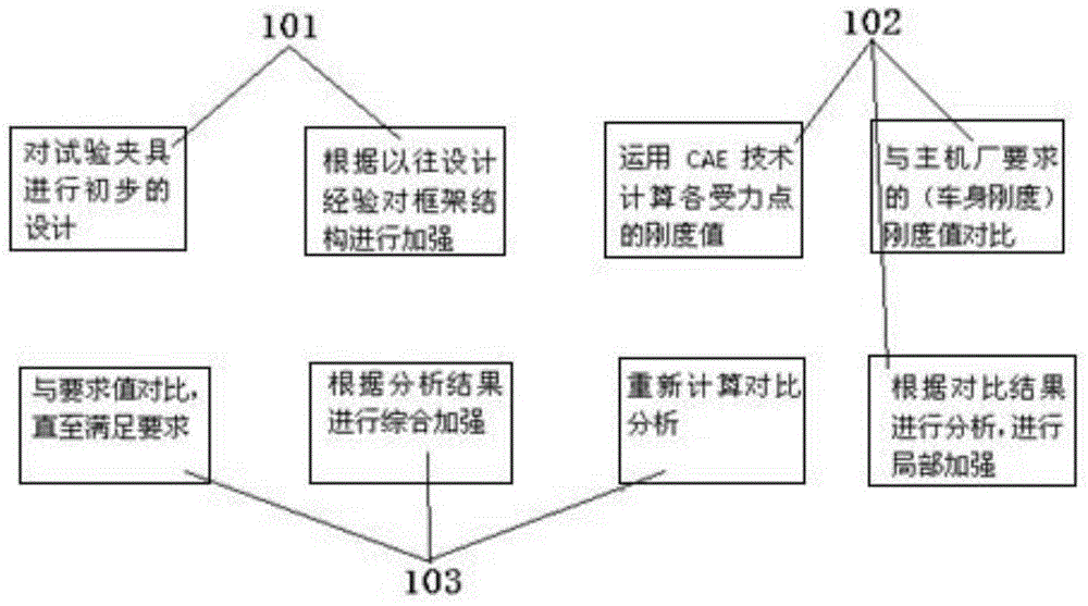

Image

  • Light frame type rear torsion beam test device and design method thereof
  • Light frame type rear torsion beam test device and design method thereof

Examples


Embodiment Construction

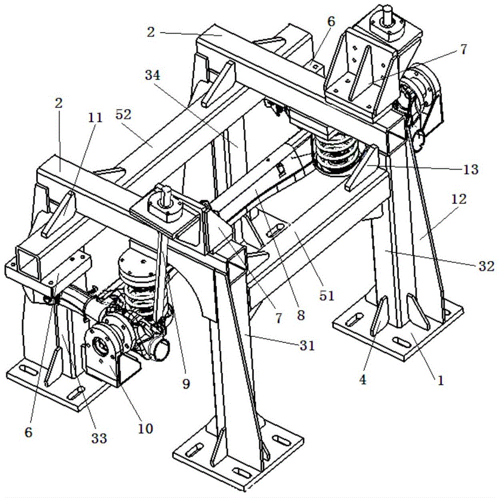
[0014] The present invention will be described in detail below in conjunction with accompanying drawing: figure 1 As shown, the present invention includes a bracket mounting plate 1, a column made up of a first column 31, a second column 32, a third column 33, and a fourth column 34, a beam made up of a first beam 51, a second beam 52, and a vertical beam. Beam 2, the support mounting plate 1 is fixed on the bottom end of the column, the first reinforcement block 4 is welded between the support mounting plate 1 and the column; the four columns are distributed in a rectangular shape, and the vertical beam 2 respectively fixed on the first column 31, the third column 33 and the second column 32, the fourth column 34, between the first column 31, the second column 32 is fixed with the first beam 51, the third column 33, A second crossbeam 52 is fixed between the fourth column 34 and the vertical beam 2, and the two ends of the second crossbeam 52 extend between the two vertical b...


PUM


Abstract

The invention relates to a light frame type rear torsion beam test device and a design method thereof. The light frame type rear torsion beam test device comprises support mounting plates, upright columns, cross beams and vertical beams; the support mounting plates are fixed to the bottom ends of the upright columns; first reinforcing blocks are welded between the support mounting plates and the upright columns; the four upright columns are distributed in a manner that the four upright columns can form a rectangle; one vertical beam is fixed to the first upright column and the third upright column, and the other vertical beam is fixed to the second upright column and the fourth upright column; the first cross beam is fixed between the first upright column and the second upright column; the second cross beam is fixed between the third upright column and the fourth upright column; two ends of the second cross beam extend out from a space between the two vertical beams; mounting blocks are fixed to the lower parts of the two ends of the second cross beam; and a shock absorber support mounting block is fixed to the vertical beams respectively. The light frame type rear torsion beam test device of the invention has the advantages of simple structure, reliable use and short design and production cycles, and can meet requirements of test requirements.

Description

technical field [0001] The invention belongs to the technical field of auto parts test devices, in particular to a light frame type rear torsion beam test device and a design method thereof. Background technique [0002] In order to achieve the effect of the performance test in the rear torsion beam bench test of an automobile, it is generally required that the stiffness of the connection point of the test fixture be greater than or equal to the stiffness of the car body. In order to ensure the rigidity of the fixture, thick steel plates are often used to build the test fixture; some even directly use the wide-flange H-shaped steel used to build the column of the house to make the fixture frame to meet the rigidity requirements. There are the following defects: 1. For different test conditions, the same test piece has multiple different force application points. The plan of steel plate construction is to get away from each force application position, and the design and manuf...

Claims


Application Information

Patent Timeline
Patent Type & Authority Applications(China)
IPC IPC(8): G01M17/007
Inventor 邱宝象徐祖锋是兆吉施永全资小林张俨黄建根
Owner ZHEJIANG WANXIANG SYST
Learn More