Supercharge Your Innovation With Domain-Expert AI Agents!

Suction device for spine surgery

An aspirator, surgical technology, applied in the direction of suction instruments, etc., can solve problems such as inconvenience of use, and achieve the effect of convenient use

Inactive Publication Date: 2022-03-25
驻马店市中医院
View PDF1 Cites 0 Cited by
  • Summary
  • Abstract
  • Description
  • Claims
  • Application Information

AI Technical Summary

Problems solved by technology

[0002] CN 105797223 A discloses a suction device, which includes: a sleeve, a joint is formed at one end, an insertion groove is provided on the side wall of the other end, and an axially penetrating suction pipe is provided inside the sleeve The suction channel, the insertion groove communicates with the suction channel; the limit block, which is located in the insertion groove, and the limit block has a limit groove; the suction handle, which can be slidably and sealingly inserted into the In the above-mentioned suction channel, the suction handle has axially arranged limiting ribs, and the outer edge of the limiting ribs is provided with a plurality of buckle grooves at intervals, and the buckle grooves are buckled on the In the limit groove; the suction handle of the present invention can realize precise position control in the casing, and after the volume of the suction channel is positioned, the suction handle can be self-maintained in the casing, which is very convenient In addition, the suction operation is easy to cause the retraction phenomenon of the suction device in the suction state, which will affect the operation operation. However, the suction chamber is limited by the buckle groove and the limit groove. Such a limit method will only The aspirator can only be stopped at the corresponding position, and the aspirator cannot be stopped at any position it wants, which is inconvenient to use

Method used


Image

  • Suction device for spine surgery
  • Suction device for spine surgery
  • Suction device for spine surgery

Examples


Embodiment 1

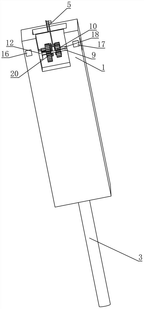
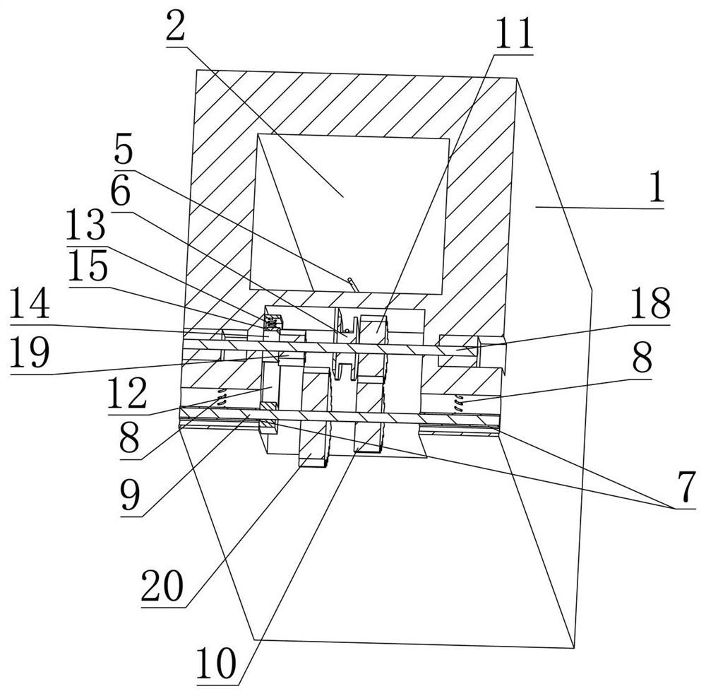
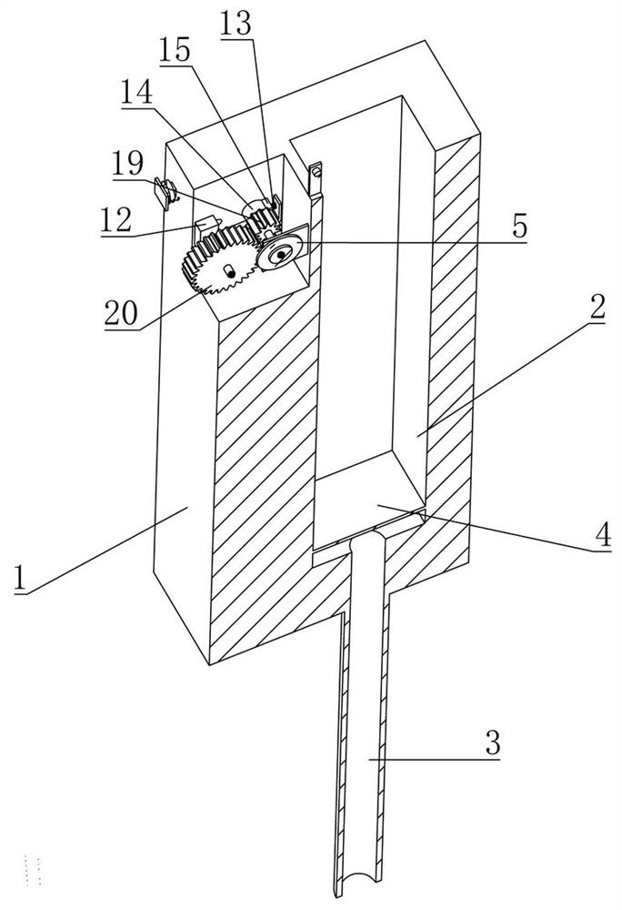
[0027] Embodiment one, with reference to figure 1 As shown, the present invention includes a fixed block 1, a suction channel 3 fixedly installed at the bottom of the fixed block 1, a suction cavity 2 is provided on the fixed block 1, and the suction cavity 2 communicates with the suction channel 3, and the medical personnel use the suction channel 3 When the device is installed, the blood in the spine can be sucked into the suction chamber 2 through the suction channel 3, thereby exposing the spine that needs to be operated on, which is convenient for doctors to operate. figure 2 As shown, the first sliding block 7 is longitudinally slidably installed on the fixed block 1, the first spring 8 is arranged between the first sliding block 7 and the fixed block 1, the first sliding block 7 is rotatably equipped with a first shaft 9, and the first On the shaft 9, the first gear 10 is fixedly installed coaxially, and the second gear 11, which is engaged with the first gear 10, is i...


PUM


Abstract

The invention belongs to the field of medical equipment, and provides a spinal surgery aspirator which comprises a fixing block. The suction cavity is formed in the fixed block; the suction channel is communicated with the suction cavity and is fixedly mounted at the lower end of the fixed block; the second sliding block is vertically installed on the suction cavity in a sliding mode, and the second sliding block is connected with a first winding wheel rotationally installed on the fixed block through a first rope belt; the first sliding block is longitudinally mounted on the fixed block in a sliding manner; the first spring is arranged between the first sliding block and the fixed block; the first shaft is rotationally installed on the fixing block and extends transversely, a first gear is coaxially and fixedly installed on the first shaft, a second gear rotationally installed on the fixing block is installed on the first gear in a meshed mode, and the first gear and the first winding wheel coaxially and synchronously rotate; the third sliding block is longitudinally mounted on the fixed block in a sliding manner; the invention provides an aspirator for spine surgery. The aspirator can be stopped at any position.

Description

technical field [0001] The invention belongs to the field of medical equipment, in particular to an aspirator for spinal surgery. Background technique [0002] CN 105797223 A discloses a suction device. The suction device includes: a sleeve, a joint is formed at one end, and an insertion groove is provided on the side wall of the other end. The suction channel, the insertion groove communicates with the suction channel; the limit block, which is located in the insertion groove, and the limit block has a limit groove; the suction handle, which can be slidably and sealingly inserted into the In the above-mentioned suction channel, the suction handle has axially arranged limiting ribs, and the outer edge of the limiting ribs is provided with a plurality of buckle grooves at intervals, and the buckle grooves are buckled on the In the limit groove; the suction handle of the present invention can realize precise position control in the casing, and after the volume of the suction ...

Claims


Application Information

Patent Timeline
Patent Type & Authority Applications(China)
IPC IPC(8): A61M1/00
Inventor 张海超王会丽
Owner 驻马店市中医院
Features
  • R&D
  • Intellectual Property
  • Life Sciences
  • Materials
  • Tech Scout
  • Unparalleled Data Quality
  • Higher Quality Content
  • 60% Fewer Hallucinations
Learn More