Raw material cleaning device for clinopodium polycephalum tablet production

A cleaning device and a technology for breaking blood flow tablets, which are applied in the directions of cleaning methods using liquids, cleaning methods and utensils, chemical instruments and methods, etc., can solve the problems of cumbersome operations, inconvenient extraction of medicinal materials, etc., to save water resources, shorten the time Long cleaning time and cost saving effect

Pending Publication Date: 2022-03-25
HUIYINBI GROUP ANHUI PHARMA
1 Cites 0 Cited by

AI-Extracted Technical Summary

Problems solved by technology

[0004] In the prior art medicinal material raw material cleaning device, after the medicinal material is cleaned, the staff needs to take out the medicinal material from one end of the cle...

Method used

As mentioned above, the raw materials that need to be cleaned by the next batch are neatly spread on the sieve plate 143, and the mobile pre-cleaning box 142 is to the bottom of the cleaning cylinder, and the raw material on the sieve plate 143 is drenched by the water flowing out of the cleaning cylinder. Washing, preliminary removal of impurities such as soil on the raw material, is conducive to the subsequent cleaning of the raw material, shortens the cleaning time, saves water resources, and saves costs. The muddy water in the pre-cleaning tank 142 can be discharged in time through the outlet hose 146 .
In the present embodiment, as shown in figure 1-6, a kind of raw material cleaning device for the production of broken blood slices includes a support portion, the support portion includes a support plate 2, and the support plate 2 below is provided with a drive half cylinder 7a and The driven half cylinder 7b, the inner ends of the driving half cylinder 7a and the driven half cylinder 7b are all fixed with a turning pl...

Abstract

The invention relates to the field of clinopodium polycephalum tablet production, in particular to a raw material cleaning device for clinopodium polycephalum tablet production, which comprises a supporting part, the supporting part comprises a supporting plate, a driving half cylinder and a driven half cylinder are arranged below the supporting plate, and turning plates are fixed at the inner ends of the driving half cylinder and the driven half cylinder; the supporting plate is provided with an opening and closing mechanism used for controlling opening and closing of the driving half cylinder and the driven half cylinder. A power part is connected to the opening and closing mechanism and used for controlling and driving the half cylinders to rotate; by adding the driving half cylinder 7a, the driven half cylinder 7b, the opening and closing mechanism, the spraying mechanism and the like, after raw materials in the cleaning cylinder are cleaned, the opening and closing mechanism is controlled, so that the driving half cylinder 7a and the driven half cylinder 7b are gradually away from each other, a worker stands between the driving half cylinder 7a and the driven half cylinder 7b, the raw materials can be taken out, the worker can take out the raw materials conveniently, and operation is simple.

Application Domain

Cleaning using liquids

Technology Topic

Clinopodium polycephalumStructural engineering +3

Image

  • Raw material cleaning device for clinopodium polycephalum tablet production
  • Raw material cleaning device for clinopodium polycephalum tablet production
  • Raw material cleaning device for clinopodium polycephalum tablet production

Examples

  • Experimental program(2)

Example Embodiment

[0031] Example 1
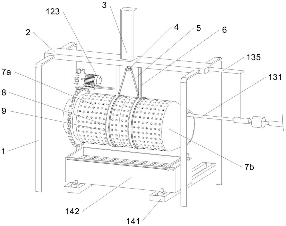
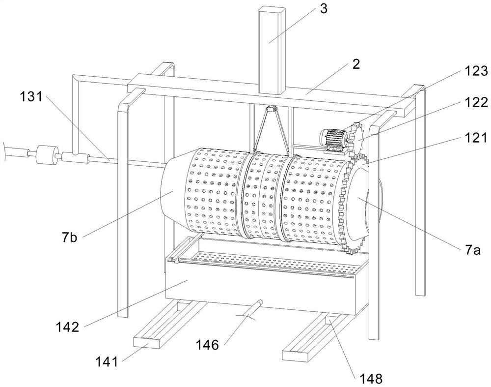
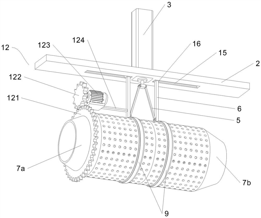
[0032] In this embodiment, as shown in FIG. The inner end of the cartridge 7b, the driving half tube 7a, and the slave half-cylinder 7b are fixed, and the arrangement of the plurality of turntable plates 17 is conducive to the dispersion and flip of the raw material, preventing the raw material accumulation, improves the cleaning effect, support plate. 2 is mounted on the mounting mechanism for controlling the driving half tube 7a, from the movable half-cylinder 7b; the power component 12 is connected to the opening and closing mechanism for controlling the driving half tube 7a;
[0033] The opening and joint mechanism includes a support ring 8 fixed to the driving half tube 7a and the outer wall of the drive halfway 7b. The outer ends of the two support ring 8 are rotated to be connected to the rotating ring 9, and the top end of the two rotation ring 9 is fixed. There is a connecting rod 6, and the top end of the two connecting rods 6 is slidably connected to the support plate 2, and the lower portion of the two connecting rods 6 rotates to be connected to the shrink rod 5, and the other end of the two shrink rod 5 rotates the connection. A connecting block 4, the tip of the connecting block 4 is connected to the hydraulic rod 3, and the hydraulic rod 3 and the support plate 2 are fixed.
[0034] In the above, the driving half tube 7a and the slave are combined, and the feedstock is placed in the cleaning barrel, and the power component 12 drives the cleaning barrel to rotate, thereby driving the raw material in the cleaning bar, and controls the sprinking mechanism. 13. After the purge is completed; after the cleaning is completed, the collecting cartridge or collecting bucket is moved under the cleaning tube, and the opening and closing mechanism is activated, that is, the hydraulic rod 3 is activated, and the connecting block 4 is moved down, the bottom end of the shrink rod 5 can be moved. Extension to the outside, drive the two connecting rods 6 to move outward, so that the driving half tube 7a and the slave half tube 7b are moved and separated from the sides, respectively, and when the driving half tube 7a and the driven half-cylinder 7b are present after a certain spacing. The staff stands at the spacing position, and the driving half tube 7a can be taken out from the raw materials from the movable half-cylinder 7b, making it easy to operate the raw material.
[0035] In this embodiment, the support portion further includes four support rods, and the outer end of the support plate 2 is fixed to one end of the four support rods 1.
[0036] In this embodiment, the inner end of the driving half tube 7a is fixed in the circumferential direction thereof, and the position of the plurality of guide column 10 is opened in the position of the inner end of the dynamic half-cylinder 7b; the guide post 10 Plug the pilot hole 11 to control the rotation of the drive half-tube 7b as the drive half tube 7b is rotated, and since the limit of the guide post 10 is rotated, the secondary cylinder 7b is also followed. Turn.
[0037] In this embodiment, the power component 12 includes a tooth ring 121 fixed to the outer wall of the driving half tube 7a, and the top end of the tooth ring 121 engages the gear 122, and the motor 123 is connected at one end of the gear 122, The motor 123 is fixed to the connecting rod 6 on the driving half tube 7a by the mounting plate 124.
[0038] In the above, the activation motor 123 can be rotated by rotating the gear 122, and the tooth ring 121 meshed with the gear 122 rotates, i.e., the cleaning tube can be rotated.
[0039]In this embodiment, the top end of the two connecting rods 6 is fixed having a slider two 16 in the bottom end of the support plate 2, and there is a sliding groove 2 15; the slider 2 16 is slidable The corresponding chute segment is within 2 15.
[0040] In this embodiment, the driving half tube 7a and the spray mechanism 13 for cleaning the feedstock is mounted to the feedstock, and the spray mechanism 13 includes an insertion driving half tube 7a, from the semi-tube 7b The water supply pipe 131, the bottom end of the water pipe 131 is uniformly connected to the mounting, and the water pipe 131 extends from the one end of the driving half tube 7a and communicates with the water hose 134, and the output The water pipe 131 and the support plate 2 are fixed by the mounting rod 135, and the water pump 133 is provided on the water pipe 131.
[0041] In the above, during the cleaning cartridge rotation, the starting water pump 133 (the water pump 133 can be mounted in the surrounding environment, not shown in the figure), and the water passes from the water supply hose 134 into the water pipe 131, then from the sprinkler 132 Spray, wash the raw materials in the cleaning barrel.

Example Embodiment

[0042] Example 2
[0043] On the basis of the first embodiment, the driving half tube 7a and the lower part of the driven space 7b are mounted to preliminate the raw material to be preliminarily cleaned; specifically, the pre-cleaning mechanism 14 includes a driving half-tube 7a, from The two support blocks 141 below the half-cylinder 7b slide the top end of the two support blocks 141, and the same pre-cleaning tank 142 is slidably connected, and the upper portion of the inner wall of the pre-cleaning tank 142 is fixed to place the sieve plate 143 for placing the raw material, and pre-cleaning the tank 142 The lower part of the rear wall is connected to the water hose 146; the pre-cleaning tank 142 is provided with a gathering assembly for concentrated the medicinal materials on the screen plate 143.
[0044] In terms of the above, the next batch needs to be cleaned on the screen 143, and the pre-cleaning tank 142 is moved below the cleaning tank, and the water flows out of the cleaning barrier to the raw material on the screen 143, preliminarily Remove impurities such as soil on raw materials, which is conducive to the raw materials in subsequent cleaning, shorten the cleaning time, saving water resources, saving costs, pre-cleaning the mud water in the washing tube 146 can be discharged in time.
[0045] Further, the clutch assembly includes a push plate 144 provided to a push plate 142, and the top end of the push plate 144 projects extends the pre-cleaning tank 142 and fixes the push rod 145; the front and rear side sections of the push rod 145 All of the slider 1 1411 is fixed, and the outer end of the pre-cleaning tank 142 corresponding to the position of the two slider 1411 is open, and the slider 1411 is slid to be linked to the chute 1610.
[0046] In the above, when the feedstock to the screen plate 143 is required to be cleaned into the cleaning barrel, the pre-cleaning tank 142 can be pushed and away from the cleaning barrel, and then push the push rod 145, the push plate 144 moves to one side, The feedstock on the screen plate 143 is collected. At this time, the staff can grasp the collapsed raw material into the cleaning cup, facilitating rapidizing the raw material on the screen plate 143 into the wash cylinder, and improving the cleaning efficiency.
[0047] In the present embodiment, both the top end of the two support blocks 141 is provided with a guide rail 147, and the two rail 147 slidely linked to the guide block 148, and the top end of the two guide block 148 projects out of the corresponding rail 147 and with the pre-cleaning tank 142. The bottom end is fixed; the guide block 148 and the guide rail 147 are locked by the lock screw 149, and the pre-cleaning tank 142 is prevented from being offset during operation by the locking screw 149.
[0048] All kinds of components are used in this application documentation, which can be purchased from the market. The specific connection methods of each part use routine methods such as bolts, rivets and welding in the prior art, mechanical, parts and electrical equipment. Using the conventional model in the prior art.

PUM

no PUM

Description & Claims & Application Information

We can also present the details of the Description, Claims and Application information to help users get a comprehensive understanding of the technical details of the patent, such as background art, summary of invention, brief description of drawings, description of embodiments, and other original content. On the other hand, users can also determine the specific scope of protection of the technology through the list of claims; as well as understand the changes in the life cycle of the technology with the presentation of the patent timeline. Login to view more.

Similar technology patents

Laser radar optical system with optical axis calibrating function and optical axis calibrating method

InactiveCN102353950AOptical axis alignment with high precisioneasy to operate
Owner:INST OF APPLIED ELECTRONICS CHINA ACAD OF ENG PHYSICS +1

Defrosting control method and device

ActiveCN104807132Aeasy to operateDefrost is reasonable
Owner:GREE ELECTRIC APPLIANCES INC OF ZHUHAI

Classification and recommendation of technical efficacy words

  • easy to operate
  • Shorten cleaning time

Lancet device

InactiveUS7303573B2inexpensively mass-producedeasy to operate
Owner:ABBOTT DIABETES CARE INC

Rapid and non-invasive optical detection of internal bleeding

InactiveUS20050065436A1easy to operaterapid and accurate result
Owner:HO WINSTON ZONH +2

Full-automatic automobile washing device

ActiveCN104290718Ashorten cleaning timecar wash clean
Owner:绍兴市中令汽车服务有限公司

Phosphoric acid equipment pipeline scale inhibitor

ActiveCN102874938AExtended cleaning cycleshorten cleaning time
Owner:WENGFU (GRP) CO LTD

Ultrasonic washing machine

Owner:玉环震浪超声股份有限公司
Why Eureka
Try Eureka