Clamping device and automatic detinning reel machining system with same

A clamping device and automatic processing technology, used in transportation and packaging, transportation of filamentous materials, thin material handling, etc., can solve problems such as trouble, achieve high quality and quality, and reduce the possibility of being torn off.

Pending Publication Date: 2022-03-25
NINGBO ZHONGDI INDUSTRY & TRADE CO LTD
View PDF0 Cites 0 Cited by
  • Summary
  • Abstract
  • Description
  • Claims
  • Application Information

AI Technical Summary

Problems solved by technology

[0005] In view of the above-mentioned related technologies, the inventor believes that the winding method in the related technologies requires the operator to manually connect at the initial stage of rewinding the tin removal line, which is troublesome.

Method used


Image

  • Clamping device and automatic detinning reel machining system with same
  • Clamping device and automatic detinning reel machining system with same
  • Clamping device and automatic detinning reel machining system with same

Examples


Embodiment Construction

[0052] The following is attached Figure 3-15 The application is described in further detail.

[0053] The embodiment of the present application discloses a clamping device.

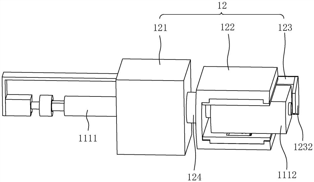
[0054] refer to image 3 , Figure 4 and Figure 5 , a clamping device includes a rotating mechanism 11 , a clamping mechanism 12 and a driving mechanism 13 .

[0055] refer to Figure 4 , the rotating mechanism 11 includes a rotating member 111 and an insertion end 112 .

[0056] refer to Figure 4 , in this embodiment, the rotating part 111 includes a rotating shaft 1111 and a placement part 1112, the rotating shaft 1111 is a cylindrical shaft, the placement part 1112 is welded to one end of the rotating shaft 1111, and the placement part 1112 is a structure formed by cutting off both sides of a cylinder, The cutting surfaces on both sides of the mounting part 1112 are the first cutting surfaces 1113, the two first cutting surfaces 1113 are parallel to each other, and the two first cutting surfa...


PUM


Abstract

The invention relates to a clamping device and an automatic detinning reel machining system with the clamping device, and relates to the field of detinning wire machining, the automatic detinning reel machining system comprises a rotating mechanism, and the rotating mechanism comprises a rotating piece; the clamping mechanism comprises a movable seat, a follower and a pressing and fixing piece; the rotating part penetrates through the movable seat, the movable seat slides in the penetrating direction of the rotating part, and the movable seat is used for allowing the rotating part to rotate; the rotating part penetrates through the follower and penetrates out to the side, away from the movable seat, of the follower, the follower is rotationally connected with the movable seat, the follower is driven to slide when the movable seat slides, and the follower is driven to rotate when the rotating part rotates; the pressing and fixing piece is arranged on the follower and comprises an abutting piece, the abutting piece is located on the side, away from the follower, of the end, stretching out of the follower, of the rotating piece, and the portion between the abutting piece and the end, stretching out of the follower, of the rotating piece is used for clamping materials. The detinning wire winding device has the effect that the detinning wire can be conveniently wound on the reel.

Description

technical field [0001] The present application relates to the field of tin removal wire processing, in particular to a clamping device and an automatic processing system for tin removal reels with the clamping device. Background technique [0002] Desoldering wire is a material used to clean up tin slag after soldering. The soldering iron heats the desoldering wire, and the tin on the circuit board will be attached to the desoldering wire to remove the tin slag on the circuit board. During production and processing, the factory will The tin removal wire is wound on a reel to make a tin removal reel, and then sold. [0003] refer to figure 1 and figure 2 , in the related art, the reel 01 used for rewinding the tin removal wire is made of plastic, the reel 01 includes a blocking piece 011 and a buckle piece 012, the blocking piece 011 and the buckle piece 012 are connected by a connecting shaft 013, and the connecting shaft There is a shaft hole 014 coaxially in 013; the b...

Claims


Application Information

Patent Timeline
IPC IPC(8): B65H67/08
CPCB65H67/08B65H2701/36
Inventor 沈梦婕李耀宗毛文来何健
Owner NINGBO ZHONGDI INDUSTRY & TRADE CO LTD
Why Eureka
Try Eureka