Side feeding corridor device
A technology of traction device and sliding device, which is applied in the direction of hoisting device, lifting device braking device, transportation and packaging, etc.
Pending Publication Date: 2022-03-25
中交二公局第六工程有限公司 +1
0 Cites 0 Cited by
AI-Extracted Technical Summary
Problems solved by technology
[0004] The invention provides a side gallery feeding device, which is used to solve the problem of inconvenient installation caused by the inability of the long section and large-tonnage pipe gallery in the prior art to be tr...
Method used
For example, the first telescopic support device can include four first telescopic cylinders 1001, and the four first telescopic cylinders 1001 are evenly distributed along the hypotenuse side of the middle part of the beam 200, and the cylinder body of the four first telescopic cylinders 1001 All are connected with crossbeam 200, and the front end of telescopic rod can be connected with a first support plate 1002, and first support plate 1002 can be steel plate, and thickness can be 20 millimeters, and the first support plate 1002 can be set at the front end of telescopic rod and can increase and slope The contact area has a certain protective effect on the slope.
In one embodiment of the present invention, the movement of crossbeam 200 preferably adopts the mode of slide plate 900 to slide, and the material of above-mentioned slide plate 900 can be polytetrafluoroethylene, and polytetrafluoroethylene is a high lubricating material, is The material with the lowest friction coefficient among the solid materials, the sliding plate 900 is laid on the slope toe of the third-level slope 103 along the extension direction of the foundation pit 100, so that it is located between the slope toe of the third-level slope 103 and the bottom of the beam 200, When the crossbeam 200 moves, the coefficient of friction between the crossbeam 200 and the sliding plate 900 can be effectively reduced and the frictional force can be reduced.
The second telescopic support device can comprise a second telescopic cylinder 1101, the second telescopic cylinder 1101 is arranged on the bottom of the top of the crossbeam 200,...
Abstract
The invention belongs to the technical field of pipe gallery segment erection, and provides a side face gallery feeding device which is characterized in that pipe gallery segments are transported to the side, provided with a pipe gallery bracket, of a cross beam through a gallery transporting vehicle, and the top of the gallery transporting vehicle is flush with the top of the pipe gallery bracket; and a first traction device located on the other side of the cross beams is used for dragging the pipe gallery sections to the pipe gallery bracket between the two cross beams from the gallery transporting vehicle. And the lifting device walks to the position above the pipe gallery section along the cross beam, lifts the pipe gallery section and conveys the pipe gallery section to the position above the preset installation position, and the pipe gallery section is lowered to the preset installation position to be installed. According to the side face gallery feeding device, the pipe gallery sections are directly dragged to the pipe gallery bracket through the gallery transporting vehicle, the pipe gallery sections can move to the position where the lifting device can conduct lifting, and the problem that at present, the pipe gallery sections cannot be transported to the position below the lifting device is solved.
Application Domain
Artificial islandsBase supporting structures +3
Technology Topic
Structural engineeringPipe +2
Image
Examples
- Experimental program(1)
Example Embodiment
[0036] In order to make the objects, technical solutions, and advantages of the present invention, the technical solutions in the present invention will be apparent from the drawings of the present invention, and it will be described in connection with the drawings of the present invention. , Not all of the embodiments. Based on the embodiments in the present invention, all other embodiments obtained without creative labor are not made in the premise of creative labor.
[0037] By below Figures 1 to 12 The side feeding device of the present invention is described.
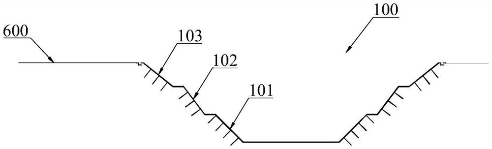
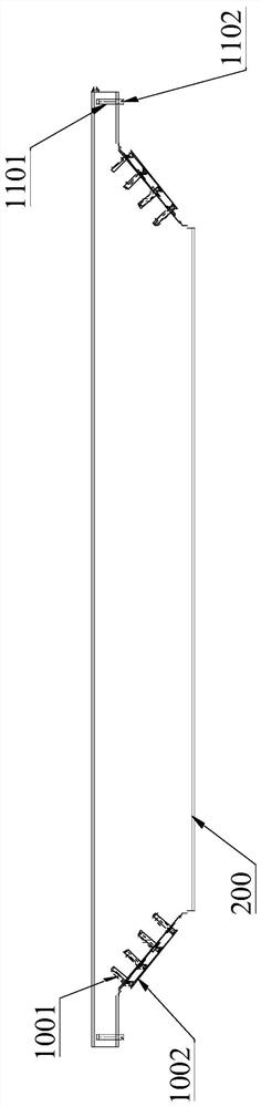
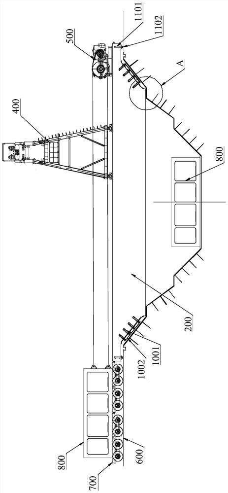
[0038] The present invention provides a side feeding device, since the gallery segment 800 needs to be mounted underground, there is a need to excavate the foundation pit 100 before the installation, and the mulgoid housing is placed above 100, and the pulley is a hanging tube poritor. Section 800 and transport it to the installation position at the bottom of the foundation pit.
[0039] In order to prevent the earth slide after the excavation pit 100, there is a need to arrange the sidewall of the foundation pit 100 into a stepped shape, the present invention to provide a structural pit 100 of the three-stage slope 103 as an example of the structure of the side feeding device. And the fancy process will be described, the slope located at the bottom of the foundation pit 100 is the primary slope 101, which is the first stage slope 101, the secondary slope 102 and the three slope 103, the third stage slope 103 is located at the top of the foundation pit 100.
[0040] A side feeding device provided by the present invention is provided to be disposed at the top of the foundation pit 100, including a pair of beam 200, a gallery bracket 300, a lifting device 400, and a first traction device 500.
[0041] The pair of beams 200 is the same and parallel to parallel, and the beam 200 is across the top of the foundation pit 100 in the width direction of the foundation pit 100, and the two ends of the beam 200 are supported on the slope of the foundation pit 100, and the two beams 200 are After the extension direction of the foundation pit 100, the top of the two beams 200 is flush and horizontally.
[0042] The lifting device 400 includes a traveling mechanism and a crane, and the traveling mechanism across the two beam 200, and the bottom of the traveling mechanism can be moved along the two beam 200, and the crane is located at the top of the traveling mechanism for a hanging tube. The gallery segment 800 and the gallery segment 800 is hoisted to the preset mounting position at the bottom of the foundation pit 100.
[0043] The gallery bracket 300 is the position where the position is positioned, and the gallery bracket 300 is disposed between the two beams 200 and is located one of the ends of the beam 200, the split bracket 300 as a starting position. The temporary support of the gallery segment 800, the traveling mechanism of the crane can drive the hoisting day to operate above the gallery bracket 300, and lifting the gallery segment 800 supported above the gallery bracket 300.
[0044] The first traction device 500 is disposed at one end of the beam 200 away from the gallery bracket 300 for traction the gallery segment 800 to the gallery bracket 300.
[0045] The side feeding apparatus provided by the present invention has the following processes:
[0046]In the transport stage, the transport pavement 600 is disposed in a direction away from the pit bracket 300 near the top of the pit 100 to the direction away from the foundation pit 100, and the gallery caravan 700 carries the gallery segment 800 to the beam by the transport pave 600. 200 is provided with one end of the gallery bracket 300, when the larbot caver 700 is loaded with the gallery segment and the gallery bus 700 is operated to the end of the beam 200, the gallery car is fixed to the beam 200, at this time, The top of the gallery 700 is parallel to the top of the gallery bracket 300, or is the bottom of the gallery segment 800 and the top of the gallery bracket 300, and in the extended direction of the foundation pit 100, the gallery segment 800 and the gallery bracket 300 is correct.
[0047] After the traction stage, when the gallery bike 700 transports the gallery segment 800 in place, the first traction device 500 is connected to the embedded member of the end portion of the gallery segment 800, and the first traction device 500 will govern the gallerogram. Section 800 is trailed from the gallery bracket 300, and the operation of the traction transfer is completed.
[0048] In the lifting stage, the traveling mechanism of the lifting device 400 drives the crane to operate along the beam 200 to above the gallery bracket 300, so that the spreader and the sprigand segment 800 of the ceiling day, will spread the spreader and the supply After the segment 800 is fixed, the crane will hang the gallery section 800, then walk the mechanism to walk through the crane to drive the gallery section 800 to the preset installation position, and then the caid will gather the gallery 800 Put it to the preset installation location.
[0049] The above-mentioned rid of the parallel gallery device, the side feeding apparatus provided by the present invention solves the prior art in the prior art to transport the gallery segment 800 directly below the pulley, which is the gallery segment The problem of inconvenience caused.
[0050] In addition, the existing gallery gallery process, the gallery needs to move on the installed completed gallery segment 800, and in the lateral feeding unit of the present invention, the gallery car is moved in the side of the foundation pit 100, Soil backfilling can be carried out in time, and speed up the construction speed.
[0051] In one embodiment of the present invention, the above-described cross-beam 200 may include a three part, a top, a central and bottom, respectively, wherein the longitudinal section of the central portion is a waist trapezoidal structure, and the waist trapezoidal distal end facing down, the like can be shaped The big end is facing up. The longitudinal section of the top is a rectangle, and the length of the top of the beam 200 is greater than the length of the large end of the waist trapezoid, and the lengths of the top ends of the beam 200 exceed the length of the portion of the middle ends of the cross-beam 200 equal. The longitudinal section of the bottom is also a rectangle, and the length of the bottom of the beam 200 is equal to the length of the bottom end of the cross member 200.
[0052] When the beam 200 is provided on the top of the foundation pit 100, both ends of the bottom of the beam 200 are supported on the slope of the slope of the top of the foundation pit 100, and the base pit 100 includes a three-stage slope as an example, the bottom of the beam 200 The end supports the slope of the three-stage slope 103 of the foundation pit 100, or is supported at the top of the secondary slope 102.
[0053] When the side feeding device provided by the present invention is completed in a certain position, it is necessary to move in the longitudinal direction of the foundation pit 100 to the next laying position. Therefore, the side feeding apparatus provided by the present invention further includes a sliding device, the sliding device can be disposed at the slope of the three-stage slope 103, or is provided at the top of the slope 102, the top of the sliding device The bottom of the beam 200 is in contact.
[0054] The sliding device may be a slide plate having a lower friction coefficient, and the bottom portion of the beam 200 is in sliding contact with the upper surface of the sliding device. Alternatively, the sliding device may be a combination of the track and the track wheel, and the track can be laid at the slope of the three-stage slope 103, extending in the extended direction of the foundation pit 100, the track wheel is disposed at the bottom of the beam 200, during movement, The track wheel scrolls on the track.
[0055] In one embodiment of the present invention, the movement of the beam 200 is preferably slidable in the manner of the sliding plate 900, and the material of the sliding plate 900 can be polytetrafluoroethylene, polytetrafluoroethylene is a high lubricating material, which is in a solid material. The material of the friction coefficient is laid in the slope of the three-stage slope 103 in the extended direction of the three-stage slope 103 along the extended direction of the three-stage slope 103, and when the beam 200 is located at the bottom of the three-stage slope 103. When moving, the friction coefficient between the beam 200 and the slide plate 900 can be effectively reduced to reduce the friction.
[0056] In one embodiment of the present invention, when the bottom of the beam 200 is supported at the slope of the three slope 103, a certain space is left between the horizontal side of the cross member 200 and the slope of the three-stage slope 103. When carrying the gallery bracket 300 connected to the beam 200, that is, when the gallery segment 800 is on the gallery bracket 300, the slope of the three-stage slope 103 is large, which may cause damage to the slope. The landslide is there.
[0057] Therefore, the first telescoping support device is provided on the side of the beam 200, when the beam 200 is carry, the movable end of the first telescopic support device projects on the slope of the three-stage slope 103 of the foundation pit 100, The pressure is dispersed onto the slope of the three-stage slope 103, and the carrier pressure of the slope of the three slope 103 is reduced, and the pressure direction is perpendicular to the slope of the three-stage slope 103, 103 three-stage slope 103 A certain protective role. When the beam 200 needs to move, the active end of the first telescopic support device is retracted, and the slope of the three slope 103 is detached, and the pressure of the beam 200 is affected by the slope of the three-stage slope 103, or the beam 200 pressure On the sliding plate 900, there is no contact with the slope and the groove top of the three-stage slope 103, thereby reducing the contact area between the beam 200 and the slope, and reduces the friction when the movement is lowered.
[0058] Further, the bottom of the top end of the top of the beam 200 is higher than the groove top of the three-stage slope 103, and there is a certain space between the slope top of the three-stage slope 103. A downstrettable second telescoping support device is provided at both ends of the top of the beam 200. When the beam 200 is carry, the second telescopic support device is protruded downward, supported at the top of the three-stage slope 103, and shares the pressure on the bottom of the cross-beam 200 on the three-stage slope 103 slope foot. When the beam 200 is moved, the second telescopic support device is retracted upward, and the top of the cross member 200 is in contact with the slope, and the pressure of the beam 200 is all from the slope of the three slope 103, or the beam 200 is pressed on the slide plate 900. None contact with the slope and the top of the three-stage slope 103, thereby reducing the contact area between the beam 200 and the slope, reducing the frictional force during movement.
[0059] In one embodiment of the present invention, the first telescopic support device and the second telescopic support device comprise at least one telescopic cylinder, the cylinder of the telescopic cylinder is connected to the beam 200, and the end connection of the telescopic rod of the telescopic cylinder is supported. plate.
[0060] For example, the first telescopic support device may include four first telescopic cylinders 1001, and the four first telescopic cylinders 1001 are uniformly distributed along the angry side of the middle portion of the beam 200, and the cylinders of the four first telescopic cylinders 1001 are both beams. 200 is connected, the front end of the telescopic rod can be connected to a first support plate 1002, and the first support plate 1002 may be a steel sheet, the thickness may be 20 mm, and the front end of the telescopic rod can increase the contact area with the slope. , Play a certain protective role in the slope.
[0061] The second telescopic support device may include a second telescopic cylinder 1101, and the second telescopic cylinder 1101 is disposed at the bottom of the top of the beam 200, the cylinder is connected to the beam 200, and the telescopic rod extends downward, and is retracted, the same is in the telescopic rod. The telescopic end is connected to a second support plate 1102, and the second support plate 1102 may be a steel sheet, the thickness may be 20 mm, and the second support plate 1102 can be increased in the front end of the telescopic rod to increase the contact area of the slope, which A certain protective role.
[0062] In a specific embodiment, the telescopic cylinder may be a hydraulic cylinder.
[0063] In one embodiment of the present invention, there is further comprising a second traction device 1200, and the second traction device 1200 is configured to move in the longitudinal direction of the foundation pit 100, moving from a mounting bit to the next installation bit.
[0064] In a specific embodiment, the above-described first traction device 500 and the second traction device 1200 can be a hoisting machine.
[0065] The winding machine body of the first traction device 500 can be disposed on one side of the beam 200 away from the gallery bracket 300, and when the traction pipe segment 800 is required, the end portion of the steel cable within the main body and the gallery section 800 The embedded part is connected.
[0066] The winding machine body of the second traction device 1200 can be disposed on one side of the beam 200 extending in the foundation pit 100, and the distance between the winding machine body and the beam 200 needs to be at least greater than one mounting position, when the movement of the beam 200, will be hoisting The end of the steel cable in the body is connected to the beam 200.
[0067] It will be noted in that the above embodiment is intended to illustrate the technical solutions of the present invention, not to limit the invention; The technical solutions described in the foregoing examples are modified, or part of the technical features in which these modifications or replacements do not allow the nature of the corresponding technical solutions from the spirit and scope of the technical solutions of the present invention.
PUM


Description & Claims & Application Information
We can also present the details of the Description, Claims and Application information to help users get a comprehensive understanding of the technical details of the patent, such as background art, summary of invention, brief description of drawings, description of embodiments, and other original content. On the other hand, users can also determine the specific scope of protection of the technology through the list of claims; as well as understand the changes in the life cycle of the technology with the presentation of the patent timeline. Login to view more.