

Direct-acting pressure relief pneumatic device, pneumatic control drain valve and water tank
A pneumatic device and pressure relief technology, used in water supply devices, flushing equipment with water tanks, buildings, etc., can solve the problems of large space occupation, unstoppable drainage, troublesome assembly and maintenance, etc., to achieve simple structure, efficient pressure relief, The effect of reduced structure
- Summary
- Abstract
- Description
- Claims
- Application Information
AI Technical Summary
Problems solved by technology
Method used
Image

Examples
Embodiment Construction
[0033] In order to make the object, technical solution and advantages of the present invention clearer, the present invention will be further described in detail below in conjunction with the accompanying drawings. It is only stated here that the words for directions such as up, down, left, right, front, back, inside, and outside that appear or will appear in the text of the present invention are only based on the accompanying drawings of the present invention, and are not specific to the present invention. limited.
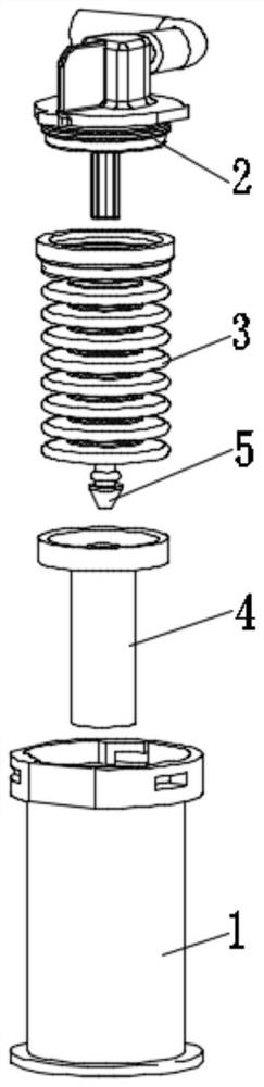
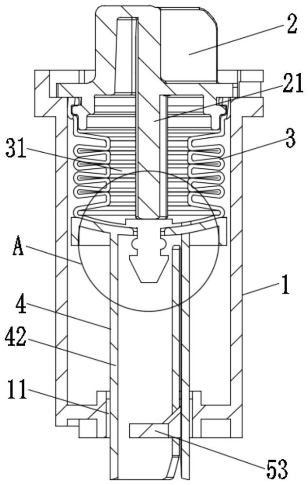
[0034] see figure 1 , figure 2 , image 3 and Figure 6 , the first embodiment of the present invention discloses a direct-acting pressure relief pneumatic device, including a housing 1, an air intake cover 2, an inflatable telescopic member 3 and a follower 4, and the air intake cover 2 is fixed to the housing The upper part of the body 1 is in sealing communication with the inflatable telescopic part 3, the air intake cover 2 is in communication with an ex...
PUM
 Abstract
Description
Claims
Application Information