Double-shaft plastering robot
A technology of robots and racks, applied in the directions of buildings and building structures, can solve problems such as the inability to effectively change the angular position of the platform, the deformation of the mechanical arm, and affect the verticality, and achieve the effect of avoiding deformation, ensuring balance, and ensuring verticality.
- Summary
- Abstract
- Description
- Claims
- Application Information
AI Technical Summary
Problems solved by technology
Method used
Image
Examples
Embodiment 1
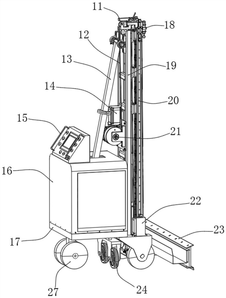
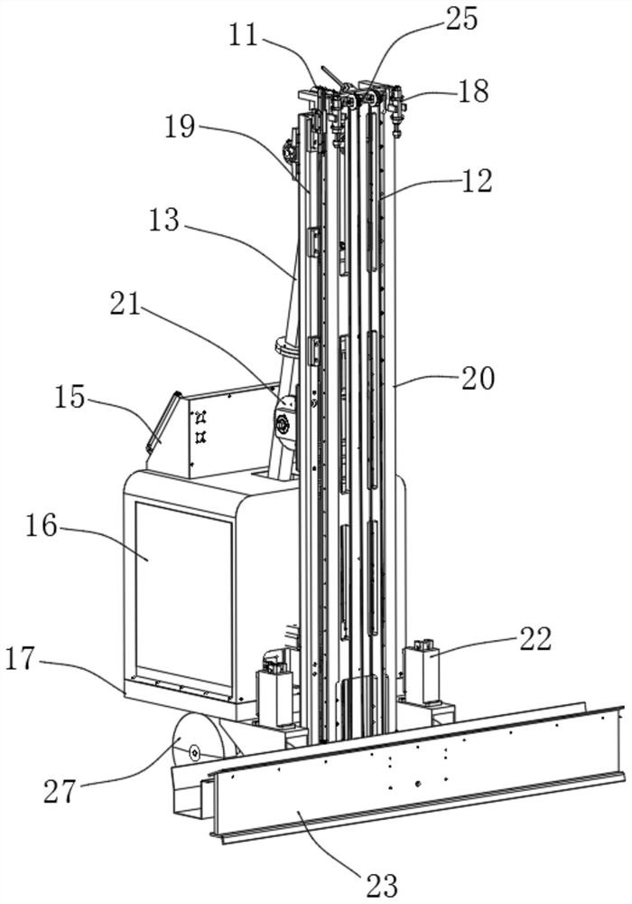
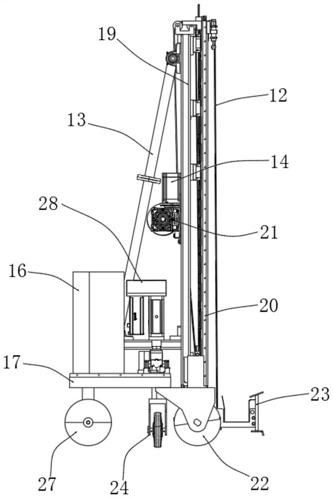
[0030] Such as Figure 1-Figure 5 As shown, this embodiment provides a two-axis plastering robot, including a platform base 17 and an adjustment platform 29, the adjustment platform 29 is installed and fixed on the upper end of the platform base 17, an angle sensor 30 is arranged above the adjustment platform 29, The rear end of the platform base 17 is provided with a rear side universal wheel 27, and the middle of the lower end of the platform base 17 is provided with an intermediate adjustment wheel 24. Metal mechanical arm 13 is arranged, and the front end of metal mechanical arm 13 is positioned at two front side moving wheels 22 and is provided with metal frame 19, and the front end of metal frame 19 is provided with front side limit frame 20, and the back of metal frame 19 The inner side of the end is provided with a geared motor 14, the outer end of the output shaft of the geared motor 14 is provided with a steel wire reel 21, the peripheral side of the steel wire reel ...
Embodiment 2
[0033] Such as figure 1 , figure 2 , Figure 4 and Figure 5 As shown, the two sides of the adjustment platform 29 are located on the box shell 16 and are provided with inverted electric cylinders 28, and the inverted electric cylinders 28 are in a symmetrical state. Because the two inverted electric cylinders 28 are installed upside down, the metal mechanical arm 13 is effectively reduced. The lower end is supported, and the installation position of the adjustment platform 29 is closer to the platform base 17, so that the position of the metal mechanical arm 13 has also dropped to the lowest level, so that when the plastering scraper 23 is aligned, the lower end of the metal mechanical arm 13 is stressed, so that it can The deformation of the metal mechanical arm 13 is avoided, and the verticality is effectively ensured.
[0034] Wherein, the adjustment platform 29 is connected with the platform base 17 through an electric cylinder and a cardan shaft.
[0035] In the embod...
Embodiment 3
[0037] Such as figure 1 , figure 2 and image 3 As shown, the metal mechanical arm 13 is located in the middle of the upper end of the adjustment platform 29, and the two ends of the metal mechanical arm 13 are symmetrical.
[0038] Wherein, the metal frame 19 and the steel wire reel 21 are fixedly connected by screws, and the outside of the joint between the metal frame 19 and the steel wire reel 21 is on the same straight line.
[0039] Wherein, the two wheels of the rear side universal wheel 27 are connected with the wheel frame through the cross shaft, and the wheels can flexibly tilt 5° left and right.
[0040] In the embodiment, when in use, because the metal frame 19 and the steel wire reel 21 are fixedly connected by screws, the steel wire reel 21 is convenient for installation, disassembly and replacement, and the connection between the metal frame 19 and the steel wire reel 21 The outside is on the same straight line, so that there will be no hindrance during use...
PUM
 Abstract
Description
Claims
Application Information
 - R&D
- Intellectual Property
- Life Sciences
- Materials
- Tech Scout
- Unparalleled Data Quality
- Higher Quality Content
- 60% Fewer Hallucinations
Browse by: Latest US Patents, China's latest patents, Technical Efficacy Thesaurus, Application Domain, Technology Topic, Popular Technical Reports.
© 2025 PatSnap. All rights reserved.Legal|Privacy policy|Modern Slavery Act Transparency Statement|Sitemap|About US| Contact US: help@patsnap.com


