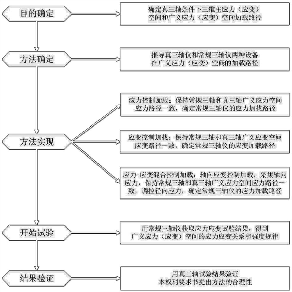
[0155] Example: such as figure 1 As shown, a method for realizing three-dimensional stress or strain path using a conventional triaxial instrument, which includes the following steps: determining the test program under true triaxial conditions in three-dimensional principal stress, principal strain space, and generalized stress, strain space the loading path of the generalized triaxial instrument and the conventional triaxial instrument in the generalized stress or strain space; control the loading method of the conventional triaxial instrument so that the loading path of the conventional triaxial instrument in the generalized stress and strain space The loading path of the axial instrument in the generalized stress and strain space is consistent; the conventional triaxial instrument is used to obtain the stress-strain test results, and the mechanical parameters of the generalized stress or strain space are obtained.
[0156] Among them: the above-mentioned loading methods for controlling the conventional triaxial instrument include stress-controlled loading or strain-controlled loading or mixed stress-strain controlled loading; In the stress space, the stress path of the conventional triaxial instrument is consistent with the stress path of the true triaxial instrument, and the loading is carried out; the strain-controlled loading is the ratio of the axial strain and the radial strain loading rate controlled by the conventional triaxial instrument, in the generalized strain space The strain path of the conventional triaxial instrument is consistent with the strain path of the true triaxial instrument, and the loading is carried out; the stress-strain mixed control loading is the axial strain control loading through the conventional triaxial instrument, and the radial stress control loading. In the stress space, the stress path of the conventional triaxial instrument is consistent with the stress path of the true triaxial instrument to implement loading.
[0157] The above-mentioned method of utilizing a conventional triaxial instrument to realize a three-dimensional stress or strain path, wherein: the above-mentioned stress control loading method is method 1 or method 2 or method 3, as follows:
[0158] Method 1: Control the decrease, constant and increase of p under the condition of keeping b constant, where p is the generalized normal stress and b is the intermediate principal stress coefficient;
[0159] Method 2: Control the change of b under the condition of keeping p constant, where p is the generalized normal stress, and b is the intermediate principal stress coefficient;
[0160] Method 3: Control the change of b while keeping p and q constant, where p is the generalized normal stress, b is the intermediate principal stress coefficient, and q is the generalized shear stress.
[0161] The above-mentioned method of utilizing a conventional triaxial instrument to realize a three-dimensional space stress or strain path, wherein: the above-mentioned strain-controlled loading method is method 4 or method 5 or method 6, as follows:
[0162] Method 4: In the principal gauge factor b ε Controlling volume strain ε under constant conditions v decrease, constant and increase;
[0163] Method 5: Maintain Volume Strain ε v Controlling the principal gauge factor b under constant conditions ε The change;
[0164] Method 6: Maintain Volume Strain ε v , shear strain γ under the condition of constant control b ε Variety;
[0165] The above two control methods for realizing the three-dimensional space stress path by using a conventional triaxial instrument, wherein: under the generalized stress condition, the relationship between the average principal stress increment dp, the generalized shear stress increment dq and the medium principal stress coefficient b and the principal stress increment Quantity to meet:
[0166] Formula 1:
[0167] Formula 2:
[0168] Formula three:
[0169] In formula 1: dσ 1 is the large principal stress increment; dσ 2 is the medium principal stress increment; dσ 3 is the small principal stress increment, and the principal stress satisfies: σ 1 ≥σ 2 ≥σ 3;
[0170] Method 1 above is:
[0171] By formula three:
[0172] Formula 4:
[0173] Substitute Equation 4 into Equation 1 and Equation 2 to simplify:
[0174] Formula five:
[0175] Formula six:
[0176] By calculating the ratio of Equation 6 and Equation 5, the arbitrary stress loading path of the true triaxial in the lower generalized stress space can be obtained. Generally, the stress control test is linear loading, so the linear loading slope is:
[0177] Formula seven:
[0178] The conventional triaxial test can only independently control the force loading in two orthogonal directions. Therefore, the relationship between the average principal stress increment dp and the generalized shear stress increment dq satisfies:
[0179] Formula eight:
[0180] Formula 9: dq=dσ 1 -dσ 3;
[0181] Equation 9 and Equation 8 compare the slope of any stress path in the generalized stress space under normal conditions:
[0182] Formula ten:
[0183] In the generalized stress space, the slope of the stress path is consistent, that is, K 1 =K 2 , you can get:
[0184] Formula eleven:
[0185] From formula eleven:
[0186] Formula 12:
[0187] formula twelve The true triaxial stress path, which means that b is constant and p changes, is as follows:
[0188] Formula 13:
[0189] Incremental is:
[0190] Formula fourteen:
[0191] From formula three and formula fourteen:
[0192] Formula fifteen:
[0193] From formula 12, formula 14 and formula 15, use Indicates that b is constant True triaxial stress path for p variation:
[0194] Formula sixteen:
[0195]
[0196] Equation 12 is the control relationship obtained under the same condition of the conventional triaxial and true triaxial stress paths in the generalized stress space, and Equation 16 is The control relational formula expressed; when the true triaxial keeps b constant loading during the loading process, then the true triaxial stress path with b constant and p changing can be realized by controlling the loading rate in the two directions of the conventional triaxial instrument according to formula 12;
[0197] Method 2 above is:
[0198] From formula 5, if it is required to realize the stress path with constant p under different b, then dp=0, we get:
[0199] Formula seventeen:
[0200] Formula 14, Formula 15 and Formula 17 can be used Indicates the true triaxial stress path with constant p under different b;
[0201] Formula eighteen:
[0202] Equation 17 is the governing equation that p is constant and b changes, and Equation 18 is The control relation expressed by Eq.17 can realize the stress loading path with constant p and variable b by controlling the loading path of the conventional triaxial instrument according to formula 17;
[0203] The method 3 is: a loading method under constant loading conditions of p and q;
[0204] In Equation 5 and Equation 6, p and q respectively correspond to σ 1 , σ 3 , b find the total differential to get:
[0205] Formula nineteen:
[0206] Formula 20:
[0207] Since p and q loads are maintained, then dp=0, dq=0, and dσ can be obtained 1 ,dσ 3 use σ 1 , σ 3 , the first expression represented by db is as follows:
[0208]
[0209] Formula 21:
[0210] Equation 21 is the control equation for p and q loading such as conventional three-axis control, and the control equation can also control the loading in the following ways:
[0211] The second expression:
[0212] because b is available Expressed as:
[0213] Formula 22:
[0214] Differentiate formula 22 to get:
[0215] Formula 23:
[0216] From the formulas 21, 22 and 23, we get dσ 1 ,dσ 3 use σ 1 , σ 3 , The second expression expressed is as follows:
[0217] Formula twenty-four:
[0218] The above-mentioned method of using a conventional triaxial instrument to realize a three-dimensional stress or strain path, wherein: under true triaxial conditions, the body strain ε v , generalized shear strain γ and medium principal strain coefficient b ε They are:
[0219] Formula 25: ε v =ε 1 +ε 2 +ε 3;
[0220] where: ε 1 is the large principal strain, corresponding to the axial strain of conventional triaxial; ε 2 is the central principal strain; ε 3 is the small principal strain, corresponding to the conventional triaxial radial strain; the principal strain satisfies ε 1 ≥ε 2 ≥ε 3;
[0221] Formula twenty-six:
[0222] Formula 27:
[0223] Under the generalized strain condition, the volumetric strain increment dε v , generalized shear strain increment dγ and medium principal strain coefficient b ε The relationship and principal strain increments satisfy:
[0224] Formula 28: dε v =dε 1 +dε 2 +dε 3;
[0225] where dε 1 is the major principal strain increment, dε 2 is the medium principal strain increment, dε 3 is the small principal strain increment;
[0226] Formula 29:
[0227] Formula thirty:
[0228] The method 4 is:
[0229] Simplified by formulas 28 and 30:
[0230] Formula 31: dε v =(1+b ε )dε 1 +(2-b ε )dε 3;
[0231] Simplified from formula 27, formula 29 and formula 30:
[0232] Formula thirty-two:
[0233] The slope of any strain path in the strain space calculated from formula 32 and formula 31 is:
[0234] Formula thirty-three:
[0235] dε under conventional triaxial conditions v , dγ are respectively:
[0236] Formula 34: dε v =dε 1 +2dε 3;
[0237] Formula thirty-five:
[0238] The slope of any strain path in the strain space under conventional triaxial control obtained from the ratio of Equation 35 and Equation 34 is:
[0239] Formula thirty-six:
[0240] Make the strain paths in the generalized strain space consistent under true triaxial control and conventional triaxial control, that is, K 1 =K 2 ,have to:
[0241] Formula thirty-seven:
[0242] Governing Equation 37 uses ε v , γ and strain Lode angle means ε v Control b under constant conditions ε Variety Set the strain path of the true triaxial; as follows:
[0243] Formula thirty-eight:
[0244] The differential expression of formula 38 is:
[0245] Formula thirty-nine:
[0246] From formulas 30 and 38, we get:
[0247] Formula 40:
[0248] From formula 37, formula 39 and formula 40, we can use ε v , γ and The governing equation for arbitrary strain path loading of the control:
[0249] Formula 41:
[0250]
[0251] Equation 37 is the control relation obtained by ensuring the same conditions for the conventional triaxial and true triaxial strain paths in the generalized strain space, and Equation 41 is ε v , γ and The control relation represented by ; when the true three-axis maintains b during the loading process ε Constant loading, then control the strain loading rate in two directions of the conventional triaxial instrument according to formula 37 to realize b ε Constant, ε v Varying true triaxial strain path;
[0252] The method 5 is:
[0253] To achieve isovolumetric loading, dε v = 0, from formula 31:
[0254] Formula forty-two:
[0255] From Equation 39, Equation 40 and Equation 42, the control equation 50 uses ε v , γ and Expressed as follows:
[0256] Formula 43:
[0257] Formula 42 is ε v constant, b ε The changing control relation, formula 43 is ε v , γ and The control relation represented by ; according to formula 42, the loading path of the conventional triaxial instrument can be controlled to realize ε v constant, b ε Varying stress loading path.
[0258] The method 6 is: ε v , the loading method under constant γ loading conditions;
[0259] From formula 25, formula 26 and formula 27:
[0260] Formula 44: ε v =(b+1)ε 1 -(b-2)ε 3;
[0261] Formula forty-five:
[0262] Equation 44, ε in 45 v , γ to ε 1 , ε 3 , b ε Total differentiation gives:
[0263] Formula 46: dε v =(1+b ε )dε 1 +(2-b ε )dε 3 +(ε 1 -ε 3 )db ε;
[0264] Formula forty-seven:
[0265] Because keep equal ε v When γ is loaded, then dε v =0, dγ=0, dε can be obtained 1 , dε 3 use ε 1 , ε 3 ,db ε The expressed expression is as follows:
[0266] The first expression:
[0267] Formula forty-eight:
[0268] Equation 48 is the conventional three-axis control ε v , etc. The governing equation of γ loading;
[0269] The second expression:
[0270] Because b can be expressed by θ as:
[0271] Formula forty-nine:
[0272] Differentiate to get:
[0273] Formula fifty:
[0274] From formulas 48, 49 and 50, dε 1 , dε 3 use ε 1 , ε 3 , The second expression expressed is as follows:
[0275] Formula fifty-one:
[0276] The above-mentioned method of using a conventional triaxial instrument to realize a three-dimensional stress or strain path, wherein: the above-mentioned stress-strain mixed control loading is to use a conventional triaxial instrument to use strain loading in the axial direction, and to use stress loading in the radial direction, keeping the conventional triaxial instrument It is consistent with the stress path of the true triaxial instrument in the generalized stress space, and the radial stress is controlled to implement the loading.
[0277] The above-mentioned method using a conventional triaxial instrument to realize a three-dimensional space stress or strain path, wherein: the above-mentioned stress-strain mixed control loading method includes the following steps:
[0278] The first step is to set the axial strain rate vload; the second step is to measure the axial stress increment dσ in real time by the conventional triaxial axial tension and compression sensor 1; The third step is to adjust the radial stress increment dσ according to formula 12 or formula 17 according to the purpose of the test 3; In the fourth step, the target stress path is achieved by stress-strain mixed controlled loading.
[0279] Specifically, taking method 2 as an example, the specific steps of using a conventional triaxial instrument to realize a three-dimensional stress or strain path are as follows:
[0280] The first step is to determine the stress path of the test scheme under the true triaxial condition in the generalized stress space. The second method of stress-controlled loading is the loading test with equal p under different b, that is, the stress path is a vertical line perpendicular to the p-axis, and the load is applied along the vertical line until the specimen is destroyed. In this test case, the effective confining pressure is set to 300kPa, that is, the stress path of the test case is the vertical line p=300kPa.
[0281] The second step is to determine the change mode of the control parameters needed to realize the above path under the conventional three-axis condition. That is, calculate the multiple relationship between the axial stress and the radial stress when the test is loaded according to Equation 17. In this case test, the loading rate of the preset radial stress is 1kPa/min, and the axial stress loading rate is determined by Equation 17 , is (b-2)/(b+1)kPa/min, 0≤b≤1, if b=0, the axial stress loading rate is -2kPa/min.
[0282] The third step is to implement loading on a conventional triaxial instrument. After entering the routine triaxial stress path test control loading program, select the control loading method as stress control loading, set the loading rate of axial stress and radial stress preset in the second step, and set the data recording method as Record data with a deformation amount of 0.01mm, and set the end condition, which is generally set at 25% of the sample height.
[0283] The 4th step, if utilize conventional triaxial apparatus to realize the test of other b values, as b=0.2,0.4,0.6,0.8,1; Return to the second step, preset radial stress loading speed is 1kPa/min, then according to the invention The formula 17 of the content calculates the axial stress loading rate as -1.5kPa/min, -8/7kPa/min, -7/8kPa/min, -2/3kPa/min and -0.5kPa/min respectively. Return to the third step to set other test parameters such as stress increase or decrease rate, start the shear test, and the test ends automatically when the test end condition is reached.
[0284] The fifth step is data collection, collation, and analysis. Collect test data, organize test data, draw and analyze whether the test control is accurate, and whether the test results conform to the objective reality; if not, analyze the test problem, find out the cause of the problem, and restart the test; The engineering properties, deformation and failure characteristics and strength parameters of the test materials are studied to study its evolution law and provide parameters for the establishment of its constitutive model.
[0285] The above-mentioned methods 1, 3, 4, 5 and 6 and the loading method under the mixed stress-strain control are similar to the implementation of the above-mentioned method 2, corresponding to the corresponding control equation, the loading process can be implemented smoothly, and the stress in the present invention can be successfully realized. path and strain path; the formulas involved in the above-mentioned technical solution can be transformed equivalently, which is equivalent to the technical solution of the present invention; and the above-mentioned embodiment is σ 1σ 3 The following formula, when σ 1σ 3 When , p increases, when σ 1 3 , p decreases; p increases or decreases, the content of the formula remains unchanged, and only the sign changes.
[0286] In addition, the triaxial test is divided into five stages: sample preparation, water head saturation, back pressure saturation, isotropic consolidation and loading shear.
[0287] Phase 1: Prepare the sample.
[0288] In order to control the similarity of the basic properties of the samples, it is necessary to control the uniformity of the density of each layer of the sample. In the sample preparation, the sand rain method is used to divide the test material into the film-supporting cylinder in 5 layers evenly to the specified height. If it does not reach the specified layer, Gently shake the outer wall of the film-supporting cylinder to make the test material fall evenly to the designated layer, repeat five times, and complete the sample loading. In order to reduce the error of artificial sample preparation and ensure the stability of the test, it is necessary to control the error of the height of the sample to not exceed 1.5mm, that is, less than 2% of the height of the sample.
[0289] Stage 2: head saturation.
[0290] In order to simplify the test model and reduce the influencing factors of the test, it is necessary to use anaerobic water to displace the air in the sample, so that the sample changes from a solid, liquid, and gas three-phase body to a solid, liquid two-phase body, and exclude compressible gas impact on test results. Head Saturation Water enters from the bottom of the sample, passes through the sample, displaces the air in the sample, and makes it flow out from the top of the sample. When the discharged water is twice the sample volume and there are no air bubbles in the discharged water, the water head is saturated. After the water head saturation is completed, the saturation of the sample must reach more than 85%.
[0291] Stage 3: backpressure saturation.
[0292] Backpressure saturation is to increase the volume of water in the pores, compress the volume of air, or dissolve under positive pressure by means of water injection under a certain confining pressure. If the carbon dioxide saturation method is used, the effect is the most obvious, because carbon dioxide has a high solubility and is easily soluble in water under the action of back pressure, which can quickly make the sample reach a saturated state. After the back pressure saturation stage is completed, the saturation of the sample is required to reach more than 98%.
[0293] Stage Four: Isotropic Consolidation.
[0294] Applying hydrostatic pressure outside the sample reduces the porosity of the sample, dissipates the pore water pressure, and increases the effective stress. It is generally believed that the isotropic consolidation stage is completed when the volume of water drained from the sample is less than 1% of the sample within 30 minutes.
[0295] Stage five: Loading the cutout.
[0296] Stage five is the method disclosed in the present invention.
[0297] Above-mentioned embodiment carried out according to method 2, its test result is as follows Figure 7-12 shown.