
Frictional wear simulation test bench of wobble friction pair

A technology for simulating test benches and friction and wear. It is used in engine testing, wear resistance testing, machine/structural component testing, etc. It can solve the problem of difficult hydraulic loading, low load stability, low spring loading accuracy, and high cost of control parts. problems, to achieve the effect of improving the level of comparability, improving the test efficiency and reducing the test cost

Inactive Publication Date: 2011-09-07
ZHONGBEI UNIV +1
View PDF5 Cites 33 Cited by
  • Summary
  • Abstract
  • Description
  • Claims
  • Application Information

AI Technical Summary

Problems solved by technology

Mechanical loading can be divided into lever loading, spring loading and direct loading of heavy objects or a combination of the above three loading forms. The structure of lever loading and direct loading of heavy objects is simple, the load is stable, there is no problem of load retention, and the loading accuracy High, but when the motion of the friction pair is unstable, it will cause vibration and shock; the vibration generated by spring loading is relatively small, but the accuracy of spring loading is not high, and it is difficult to achieve precise load adjustment
Hydraulic loading includes dynamic pressure loading and static pressure loading. Hydraulic loading is difficult to keep the load stable
Electromagnetic loading is easy to realize the automatic control of the load, but its weakness is that the cost of the control part is relatively high, and it is rarely used on the existing friction and wear testing machine

Method used


Image

  • Frictional wear simulation test bench of wobble friction pair
  • Frictional wear simulation test bench of wobble friction pair
  • Frictional wear simulation test bench of wobble friction pair

Examples


Embodiment Construction

[0028] The present invention will be further described below in conjunction with the accompanying drawings.

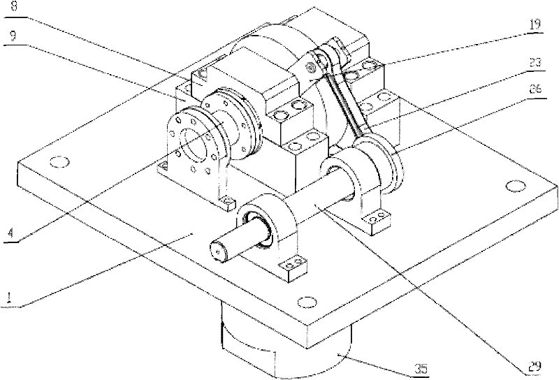
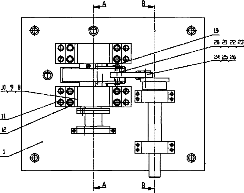
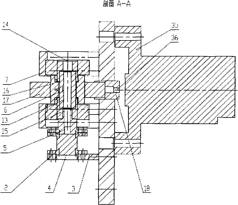
[0029] figure 1 , figure 2 and image 3 As shown, the friction and wear simulation test bench for the swing friction pair is mainly composed of a frame workbench, a spindle drive device, a friction pair simulation swing mechanism, a hydraulic loading device, a hydraulic control system, and a PC control system; spindle drive devices with different speeds will be provided It is fixed on the frame workbench 1 through the bearing seat, and the friction pair simulation swing mechanism for installing the sliding bearing 6 and the piston pin 13 in the friction pair parts is also fixed on the frame workbench 1 through the upper and lower bearing seats 8 and 9. Above, the oil cylinder 35 of the hydraulic loading system is also fixed under the frame workbench 1 by bolts. The rack table can be welded by profiles and steel plates, or it can be cast in parts and then consolidat...


PUM


Abstract

The present invention relates to a frictional wear simulation test bench of a wobble friction pair, which is mainly composed of the following components: a frame workbench, a main shaft drive unit, a friction pair simulation swing mechanism, a hydraulic loading device, a hydraulic control system and a PC control system. The PC control system of the simulation test bench collects the signals of a torque sensor, a pressure sensor and a rotating speed sensor; and can realize the following functions: controlling an amplitude and a frequency of a loading force; operating and controlling a test program; collecting, processing and storing data; displaying and printing test data and a test curve. The frictional wear test follows a system correlation principle, a principle that the temperature fields are similar, a limit principle, a principle that the wear mechanisms are same, and a wear test simulation determination standard. A practical wobble friction pair is used as a test object. The frictional wear simulation test bench of the wobble friction pair has the following characteristics: compact structure, adjustable load amplitude, adjustable rotating speed, adjustable loading frequency, capability of simulating different working conditions of an engine, and capability for measuring the frictional wear characteristics of different types of wobble friction pairs.

Description

technical field [0001] The invention belongs to the technical field of test equipment, and in particular relates to a friction and wear test bench for a sliding bearing and a shaft of an oscillating friction pair of a piston engine. technical background [0002] The friction and wear test of engine swing friction pair is usually divided into general sample test, bench test and friction pair simulation test. [0003] The general sample test is mainly used to study the friction and wear mechanism, general laws and relative wear resistance of materials. Due to the ideal test conditions, the results of this test are difficult to be directly used in a specific occasion, but the cycle is short and the conditions are easy. Good control, data repeatability and comparability. It is widely used in the experimental research of material selection and surface treatment process. The bench test is carried out under conditions closer to the actual working conditions of the friction pair, ...

Claims


Application Information

Patent Timeline
Patent Type & Authority Applications(China)
IPC IPC(8): G01N3/56G01M15/00
Inventor 赵俊生王建平原霞宋吉林樊文欣
Owner ZHONGBEI UNIV
Learn More