
Twin array Michelson optical fiber white light interference strain gage

A technology of white light interferometry and strain gauges, which is applied in the direction of instruments, scientific instruments, and optical devices, can solve the problems of small number of multiplexes, unfavorable deployment and use, and low signal-to-noise ratio of optical fiber interferometers, and achieve low cost and effective Facilitate promotion and reduce test costs

Inactive Publication Date: 2008-12-24
HARBIN ENG UNIV
View PDF1 Cites 31 Cited by
  • Summary
  • Abstract
  • Description
  • Claims
  • Application Information

AI Technical Summary

Problems solved by technology

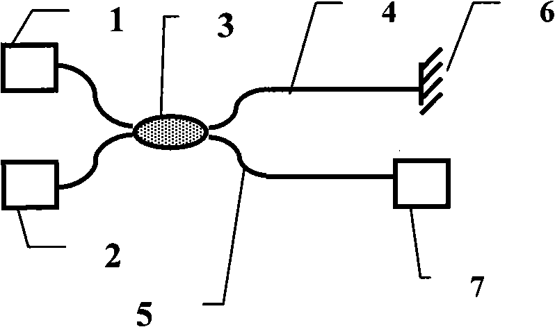
[0009] The applicant disclosed the multiplexing optical fiber interferometer and its nesting construction method in 2006 (Chinese patent publication number: CA1963399A), invented the all-fiber interferometer optical fiber and its implementation method that can construct sensor arrays and networks, and solved the problem of optical fiber The number of multiplexed interferometers is small and the structure is complex
In the low-coherence twisted Sagnac-like optical fiber deformation sensing device disclosed by the applicant in 2007 (Chinese Patent Publication No.: 101074867A), although the interferometer structure can theoretically solve the problem of anti-destruction, but because its structure is too complicated, In particular, the optical signal has too many paths, the intensity is weak, and the signal-to-noise ratio is low, which is not conducive to the deployment and use in actual measurement

Method used


Image

  • Twin array Michelson optical fiber white light interference strain gage
  • Twin array Michelson optical fiber white light interference strain gage
  • Twin array Michelson optical fiber white light interference strain gage

Examples


Embodiment

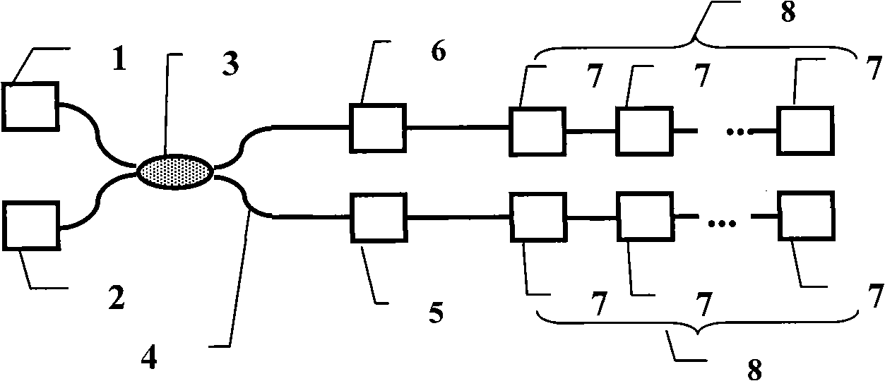
[0039] Embodiment: Utilize the scheme of the multiplexing fiber optic interferometer constructed by twin array fiber optic sensor devices, combined with image 3 , it can be seen from the figure that the multiplexed twin fiber interferometer consists of a broadband light source 1, a photodetector 2, a 3dB fiber 2×2 coupler 3, a single-mode connecting fiber 4, an optical attenuator 5, an optical delay line 6 and An array 8 of twin optical fiber sensors 7 is formed.

[0040] The optical fiber sensor 7 is composed of a section of optical fiber of any length with vertical reflective end faces with arbitrary reflectivity at both ends. The typical structure is as follows Figure 4 As shown, a section of single-mode optical fiber intercepted according to the actual measurement needs is equipped with ceramic ferrule 701 at both ends, and after the end face is polished, an optical fiber end face with a reflectivity perpendicular to the direction of transmitted light greater than 1% is ...


PUM


Abstract

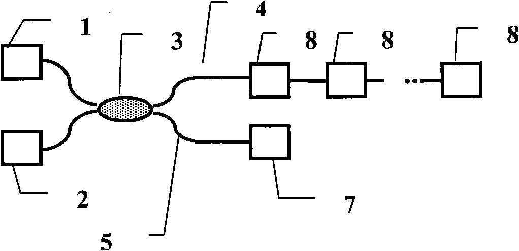
The invention provides a white light interferometer strain gauge of twin array Michelson optical fibers, which consists of a broad-band light source, an photodetector, a coupler, a single-mode connecting optical fiber, an optical attenuator, an optical delay line and a sensing array that is composed of twin optical fiber sensors, wherein, broad-band light emitted by the broad-band light source is split by the coupler, one light beam is transmitted into an array that consists of an arm optical fiber sensor by the optical attenuator, the other light beam is transmitted into the array that consists of another arm optical fiber sensor by the optical delay line, and light signals that are returned by the two arms are transmitted into the photodetector for detection and analysis by the coupler. The white light interferometer strain gauge of the twin array Michelson optical fibers is characterized in that the white light interferometer strain gauge can realize the measurement of strain and temperature at the same time, reduces the influence of temperature to the measurement by utilizing the temperature compensation technique, and simultaneously, simplifies system complexity, lowers testing cost, ensures the real-time property of testing and improves testing reliability; furthermore, the white light interferometer strain gauge has simple structure, easy implementation, low cost and price and easy acquisition.

Description

technical field [0001] The invention relates to a measuring device, in particular to an optical fiber interference strain gauge constructed based on the principle of space division multiplexing. Background technique [0002] Optical fiber interferometers using low-coherence and broadband light sources are usually called white light optical fiber interferometers. Compared with other optical fiber interferometers, in addition to their high sensitivity, intrinsic safety, and anti-electromagnetic Pressure, strain, temperature waiting to be measured for absolute measurement. Therefore, white light interference fiber optic interferometers are widely used in the measurement of physical quantities, mechanical quantities, environmental quantities, chemical quantities, and biomedical quantities. [0003] In recent years, white light interferometric sensing technology has developed vigorously. One of the hot spots is the development of a variety of optical fiber sensors and test syste...

Claims


Application Information

Patent Timeline
Patent Type & Authority Applications(China)
IPC IPC(8): G01B11/16G01K11/32G02B6/26G02B6/38
Inventor 苑立波杨军张羽
Owner HARBIN ENG UNIV
Learn More