
Current-carrying friction wear test method

A wear test and current-carrying friction technology, which is applied in the field of friction test, can solve the problems of complicated friction and wear and difficult measurement, and achieve the effects of simple operation, flexible adjustment, and improved accuracy and measurement efficiency

Pending Publication Date: 2022-03-25
TIANJIN RES INST FOR ADVANCED EQUIP TSINGHUA UNIV +1
View PDF0 Cites 0 Cited by
  • Summary
  • Abstract
  • Description
  • Claims
  • Application Information

AI Technical Summary

Problems solved by technology

When the train is running at high speed, under the influence of factors such as current and friction and wear, there will be a coupling effect of mechanical wear and current wear. The situation of friction and wear is more complicated, and it is difficult to measure effectively and accurately

Method used

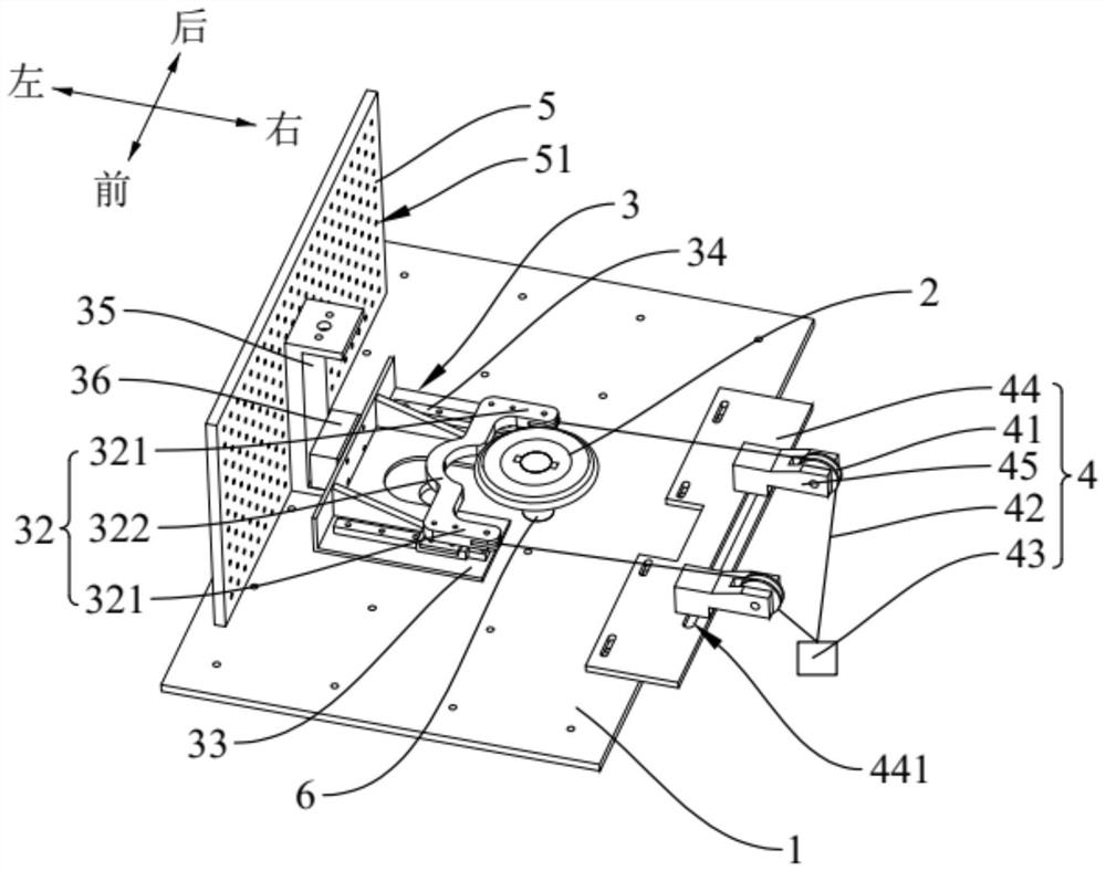
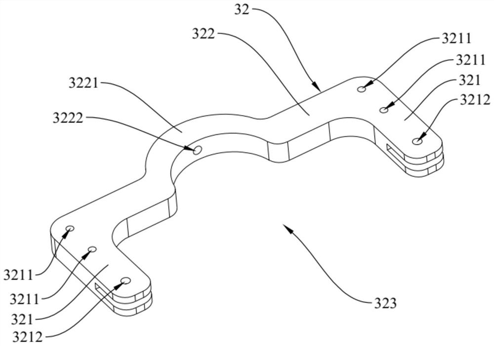

Image

  • Current-carrying friction wear test method
  • Current-carrying friction wear test method
  • Current-carrying friction wear test method

Examples


Embodiment Construction

[0031] In order to make the technical problems solved by the present invention, the technical solutions adopted and the technical effects achieved clearer, the technical solutions of the present invention will be further described below in conjunction with the accompanying drawings and through specific implementation methods. It should be understood that the specific embodiments described here are only used to explain the present invention, but not to limit the present invention. In addition, it should be noted that, for the convenience of description, only the parts related to the present invention are shown in the drawings but not all of them.

[0032] In the description of the present invention, unless otherwise clearly specified and limited, the terms "connected", "connected" and "fixed" should be understood in a broad sense, for example, it can be a fixed connection, a detachable connection, or an integrated ; It can be a mechanical connection or an electrical connection;...


PUM


Abstract

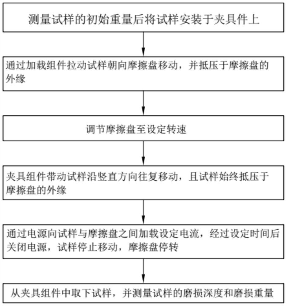
The invention relates to the technical field of friction tests, and discloses a current-carrying friction wear test method. The current-carrying friction wear test method comprises the following steps: measuring the initial weight of a sample, and mounting the sample on the clamp assembly; the loading assembly pulls the sample to move towards the friction disc and abuts against the outer edge of the friction disc. And adjusting the friction disc to a set rotating speed. The clamp assembly drives the sample to reciprocate in the vertical direction, and the sample abuts against the outer edge of the friction disc all the time. A set current is loaded between the sample and the friction disc through a power supply, the power supply is turned off after a set time, the sample stops moving, and the friction disc stops rotating. The sample is taken down from the clamp assembly, and the abrasion depth and the abrasion weight of the sample are measured. According to the current-carrying friction wear test device, the friction condition of the sample and the friction disc under the current-carrying condition can be truly simulated by adopting the current-carrying friction wear test method, the flexible adjustment of the current-carrying friction wear test device is realized, and the measurement efficiency and the accuracy of a test result are improved.

Description

technical field [0001] The invention relates to the technical field of friction tests, in particular to a current-carrying friction and wear test method. Background technique [0002] The pantograph is the electrical equipment used by the electric traction locomotive to obtain electric energy from the catenary, and is generally installed on the top of the locomotive or motor car. When the train is running at high speed, the carbon slide of the pantograph is constantly rubbing against the catenary, which supplies the train with electrical energy. [0003] In conventional friction and wear tests, the amount of wear of a sample is measured by mechanical impact or mechanical friction. The carbon sliding plate of the pantograph and the catenary is a mechanically and electrically coupled friction pair. When the train is running at high speed, the coupling effect of mechanical wear and current wear will occur under the influence of factors such as current and friction and wear. T...

Claims


Application Information

Patent Timeline
Patent Type & Authority Applications(China)
IPC IPC(8): G01N3/56
CPCG01N3/56
Inventor 郑剑锋张向军张凤龙
Owner TIANJIN RES INST FOR ADVANCED EQUIP TSINGHUA UNIV
Learn More