
Self-pressure dehumidification type power distribution cabinet

A power distribution cabinet and dehumidification technology, which is applied in the field of self-pressure dehumidification power distribution cabinets, can solve the problems of easy condensation of water droplets, complex structure, and difficulty in applying to the inner wall of the cabinet.

Active Publication Date: 2022-03-25
徐州佳联农业发展有限公司
View PDF6 Cites 2 Cited by
  • Summary
  • Abstract
  • Description
  • Claims
  • Application Information

AI Technical Summary

Problems solved by technology

[0004] However, in addition to the top of the cabinet, water droplets are also easy to condense on the inner wall of the power distribution cabinet. Once there are too many water droplets, they will converge and go down along the inner wall flow, wet the electrical components on the inner wall, and cause the internal components of the power distribution cabinet to fail, and because some electrical components will be installed on the inner wall of the cabinet, the structure is complicated, and the external condensate pipe in the above patent is difficult to apply to the inner wall of the cabinet.

Method used


Image

  • Self-pressure dehumidification type power distribution cabinet
  • Self-pressure dehumidification type power distribution cabinet
  • Self-pressure dehumidification type power distribution cabinet

Examples


Embodiment

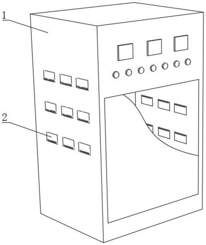
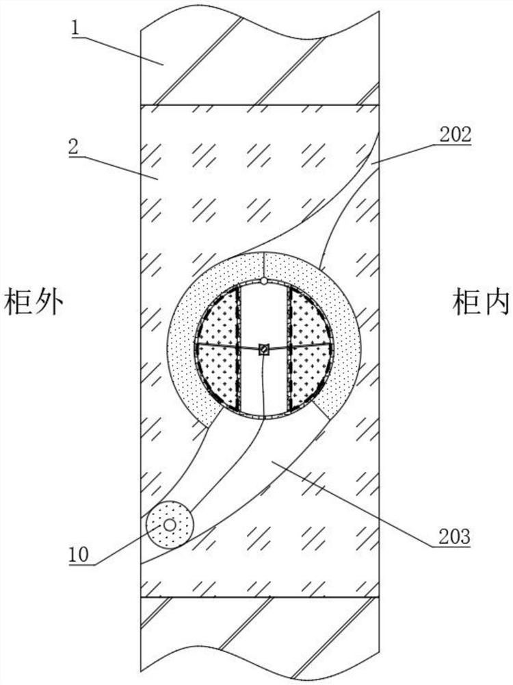
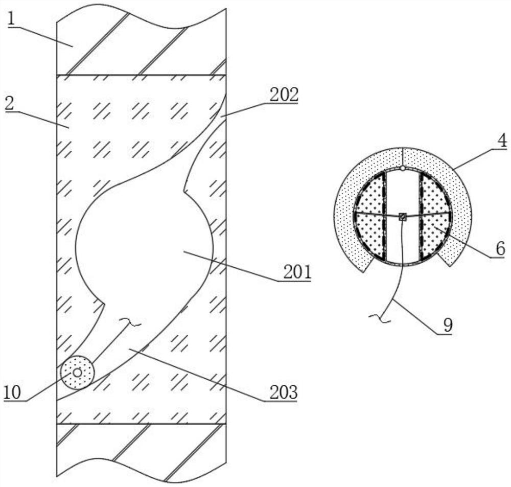
[0040] see figure 1 and figure 2 , a self-pressurized dehumidification type power distribution cabinet, including a cabinet body 1, a plurality of installation holes are opened at the side end of the cabinet body 1, and a moisture guide plate 2 is fixedly connected to the inside of the installation hole, and the inner and outer surfaces of the moisture guide plate 2 are connected with the cabinet The inner and outer surfaces of body 1 are flush, which is not easy to affect the installation and connection of internal electrical components. Please refer to figure 2 and image 3 , the interior of the moisture guide plate 2 is provided with a cylindrical cavity 201, and the upper and lower inner walls of the cylindrical cavity 201 are respectively provided with a moisture inlet hole 202 and a moisture discharge hole 203. The upper opening of the moisture inlet hole 202 communicates with the inside of the cabinet body 1, and the moisture discharge hole The lower orifice of 203 ...


PUM


Abstract

The invention discloses a self-pressure dehumidification type power distribution cabinet, and belongs to the field of power distribution cabinets, the side end of a cabinet body is provided with a moisture guide plate with a self-pressure dehumidification column, moisture condensed on the inner wall of the cabinet body is guided into the moisture guide plate, is in contact with the self-pressure dehumidification column and is absorbed by moisture absorption cotton, and when the moisture absorption cotton absorbs enough moisture, the moisture guide plate is in contact with the self-pressure dehumidification column. Water is transmitted to the expansion bag to expand the expansion bag, a pair of semicircular plates are driven to rotate and get away from each other, on one hand, the moisture absorption cotton is extruded, excessive water in the moisture absorption cotton is promoted to overflow to the outside, and the water content of the moisture absorption cotton is preliminarily reduced, and on the other hand, the semicircular plates drive the variable-pressure body to stretch and enlarge, the sealing bag is shrunk, and outside air enters the moisture discharging holes. The moisture absorption cotton and the expansion bag are accelerated to evaporate, the environment humidity in the cabinet body is reduced, and after the moisture is diffused, the sealing bag recovers the expansion state, so that external air enters the cabinet body.

Description

technical field [0001] The invention relates to the field of power distribution cabinets, more specifically, to a self-pressurized dehumidification type power distribution cabinet. Background technique [0002] Power distribution cabinets (boxes) are divided into power distribution cabinets (boxes), lighting distribution cabinets (boxes), and metering cabinets (boxes), which are the final equipment of the power distribution system. The power distribution cabinet is a general term for the motor control center. The power distribution cabinet is used in the occasions where the load is relatively scattered and there are few circuits; the motor control center is used in the occasions where the load is concentrated and there are many circuits. They distribute the electric energy of a certain circuit of the upper-level power distribution equipment to the nearest load. This level of equipment shall provide protection, monitoring and control of the load. [0003] Patent No. CN2021...

Claims


Application Information

Patent Timeline
Patent Type & Authority Applications(China)
IPC IPC(8): H02B1/28H02B1/56H02B1/30
CPCH02B1/28H02B1/565H02B1/30Y02A30/14
Inventor 朱丛一王寅竹
Owner 徐州佳联农业发展有限公司
Learn More