Method and apparatus in node used for wireless communication

A wireless communication and wireless signal technology, applied in the field of nodes and devices used for wireless communication, can solve problems such as uncertain duration, achieve the effects of reducing overhead, accurate LBT results, and reducing complexity

Pending Publication Date: 2022-03-25
SHANGHAI LANGBO COMM TECH CO LTD
View PDF0 Cites 0 Cited by
  • Summary
  • Abstract
  • Description
  • Claims
  • Application Information

AI Technical Summary

Problems solved by technology

Therefore, the duration of Cat 4 LBT is indeterminate

Method used


Image

  • Method and apparatus in node used for wireless communication
  • Method and apparatus in node used for wireless communication
  • Method and apparatus in node used for wireless communication

Examples


Embodiment 1

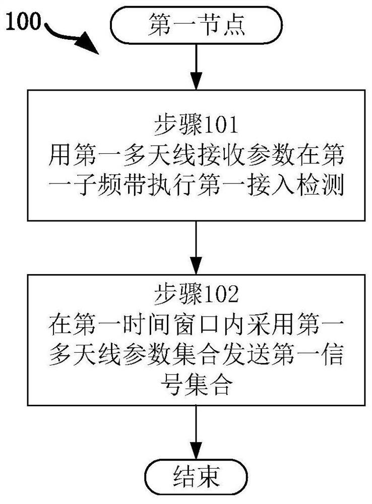
[0068] Embodiment 1 illustrates the processing flowchart of the first node of an embodiment of the present application, as shown in the attached figure 1 shown. in the attached figure 1 In , each box represents a step. In particular, the order of the steps in the blocks does not represent a specific chronological relationship between the various steps. In Embodiment 1, the first node in this application uses the first multi-antenna reception parameter to perform the first access detection in the first sub-band in step 101, and uses the first multi-antenna reception parameter in the first time window in step 102. The set of antenna parameters transmits a first set of signals. Wherein, the first multi-antenna parameter set includes first multi-antenna related parameters, the first signal set includes a first wireless signal, and the first wireless signal is sent by the first multi-antenna related parameters; the first multi-antenna related parameters An access detection is u...

Embodiment 2

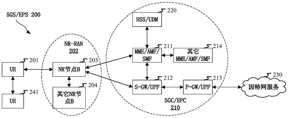
[0116] Embodiment 2 illustrates a schematic diagram of a network architecture according to the present application, as attached figure 2 shown.

[0117] attached figure 2A diagram illustrating a network architecture 200 of 5G NR, LTE (Long-Term Evolution, long-term evolution) and LTE-A (Long-Term Evolution Advanced, enhanced long-term evolution) systems. The 5G NR or LTE network architecture 200 may be referred to as 5GS (5G System, 5G System) / EPS (Evolved Packet System, Evolved Packet System) 200 or some other suitable terminology. 5GS / EPS 200 may include one or more UE (User Equipment, user equipment) 201, NG-RAN (next generation radio access network) 202, 5GC (5G Core Network, 5G core network) / EPC (Evolved PacketCore, evolution Packet Core) 210, HSS (Home Subscriber Server, Home Subscriber Server) / UDM (Unified Data Management, Unified Data Management) 220 and Internet Service 230. 5GS / EPS can be interconnected with other access networks, but not shown for simplicity Th...

Embodiment 3

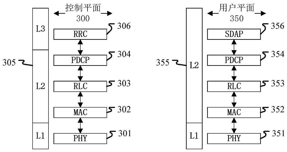
[0135] Embodiment 3 shows a schematic diagram of an embodiment of a wireless protocol architecture of a user plane and a control plane according to the present application, as shown in the attached image 3 shown. image 3 is a schematic diagram illustrating an embodiment of a radio protocol architecture for a user plane 350 and a control plane 300, image 3 Three layers are used to show the first node (RSU in UE or V2X, vehicle equipment or vehicle communication module) and the second node (gNB, RSU in UE or V2X, vehicle equipment or vehicle communication module), or two Radio protocol architecture of the control plane 300 between UEs: Layer 1, Layer 2 and Layer 3. Layer 1 (L1 layer) is the lowest layer and implements various PHY (Physical Layer) signal processing functions. The L1 layer will be referred to herein as PHY 301 . Layer 2 (L2 layer) 305 is above PHY 301, through which PHY 301 is responsible for the link between the first node and the second node and the two UE...


PUM


Abstract

The invention discloses a method and an apparatus in a node used for wireless communication. The first node performs a first access detection in a first sub-band using a first multi-antenna reception parameter and transmits a first set of signals within a first time window using a first set of multi-antenna parameters. Wherein the first multi-antenna parameter set comprises a first multi-antenna related parameter, the first signal set comprises a first wireless signal, and the first wireless signal is sent by the first multi-antenna related parameter; the first access detection is used for determining first detection power; the first detection power less than a first power threshold is used for determining that the first multi-antenna related parameter can be used for wireless transmission in the first time window; the spatial correlation of the first multi-antenna related parameter and the first multi-antenna receiving parameter is used for determining the first detection power. According to the method provided by the invention, interference conditions in different spatial directions can be accurately detected.

Description

technical field [0001] The present application relates to a transmission method and device in a wireless communication system, in particular to a transmission scheme and device related to unlicensed spectrum in wireless communication. Background technique [0002] The application scenarios of future wireless communication systems are becoming more and more diversified, and different application scenarios put forward different performance requirements for the system. In order to meet the different performance requirements of various application scenarios, the new air interface technology (NR, New Radio) (or Fifth Generation, 5G) to conduct research, passed the WI (Work Item, work item) of NR at the 3GPP RAN#75 plenary meeting, and started to standardize NR. [0003] A key technology of NR is to support beam-based signal transmission, and its main application scenario is to enhance the coverage of NR devices working in millimeter wave frequency bands (such as frequency bands ...

Claims


Application Information

Patent Timeline
Patent Type & Authority Applications(China)
IPC IPC(8): H04W16/28H04W24/02H04W24/08H04W52/02
CPCH04W16/28H04W24/02H04W24/08H04W52/02Y02D30/70
Inventor 张晓博
Owner SHANGHAI LANGBO COMM TECH CO LTD
Why Eureka
Try Eureka