Supercharge Your Innovation With Domain-Expert AI Agents!

Campus intelligent lighting control system

A lighting control system and intelligent technology, applied in the direction of energy-saving control technology, electrical components, etc., can solve the problems of not being able to control the area lighting at the first time, users not being able to get the lighting effect, and monitoring human resources troublesome, so as to avoid program errors, The effect of avoiding waste and differentiated control

Pending Publication Date: 2022-03-25
幸敏
View PDF7 Cites 0 Cited by
  • Summary
  • Abstract
  • Description
  • Claims
  • Application Information

AI Technical Summary

Problems solved by technology

[0002] With the progress of society, people continue to pay attention to education. Education is a basic national policy of our country. The whole society has invested great attention and huge manpower and material resources on education. The number of schools is also increasing. At the same time, the field of lighting As the most energy-consuming area in campus daily life, it is necessary to adopt an effective lighting control system. However, most of the current campus lighting control systems use various sensors to detect within a range, and then realize intelligent control of campus lighting. However, this This kind of lighting controlled by sensors easily conflicts with people's control intentions indoors, resulting in users not being able to get good lighting effects, and the campus lighting control system is controlled by centralized control from the monitoring center. The power supply of the lighting will be disconnected. When the relevant personnel need to illuminate the area, they need to notify the monitoring center for control, which brings trouble to the monitoring human resources, and cannot control the lighting of the area immediately, so it needs to be improved

Method used


Image

  • Campus intelligent lighting control system
  • Campus intelligent lighting control system
  • Campus intelligent lighting control system

Examples


Embodiment 1

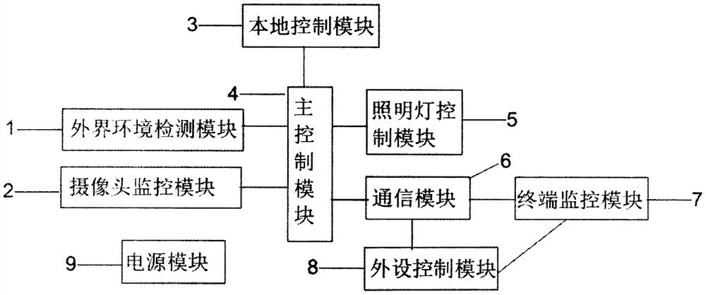
[0023] Example 1: see figure 1 , the embodiment of the present invention provides a campus smart lighting control system, the campus smart lighting control system includes: external environment detection module 1, camera monitoring module 2, local control module 3, main control module 4, lighting control module 5, communication Module 6, terminal monitoring module 7, peripheral control module 8, power supply module 9;

[0024] Specifically, the external environment detection module 1 is used to detect the intensity of external light, to judge whether there are people around the smart light, and to output detection data;

[0025] Camera monitoring module 2, used for monitoring image information within the camera range and outputting image data;

[0026] The local control module 3 is used to select the intelligent control and manual control of the lighting lamps in the classroom through the switch and output the control command;

[0027] The main control module 4 is connected ...

Embodiment 2

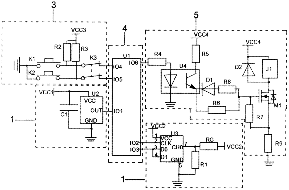
[0034] Embodiment 2: On the basis of Embodiment 1, please refer to figure 2 and image 3 , in a specific embodiment of the campus intelligent lighting control system described in the present invention, such as figure 2 As shown, the external environment detection module 1 includes an infrared sensor U2, a first capacitor C1 and a first power supply VCC1; the main control module 4 includes a first controller U1;

[0035] Specifically, the power supply end of the infrared sensor U2 is connected to the first power supply VCC1 and one end of the first capacitor C1, the other end of the first capacitor C1 and the ground end of the infrared sensor U2 are grounded, and the output end of the infrared sensor U2 is connected to the first The first IO terminal of the controller U1.

[0036] Further, the external environment detection module 1 also includes an AD converter U3, a photoresistor RG, a first resistor R1 and a second power supply VCC2;

[0037] Specifically, the first ter...

Embodiment 3

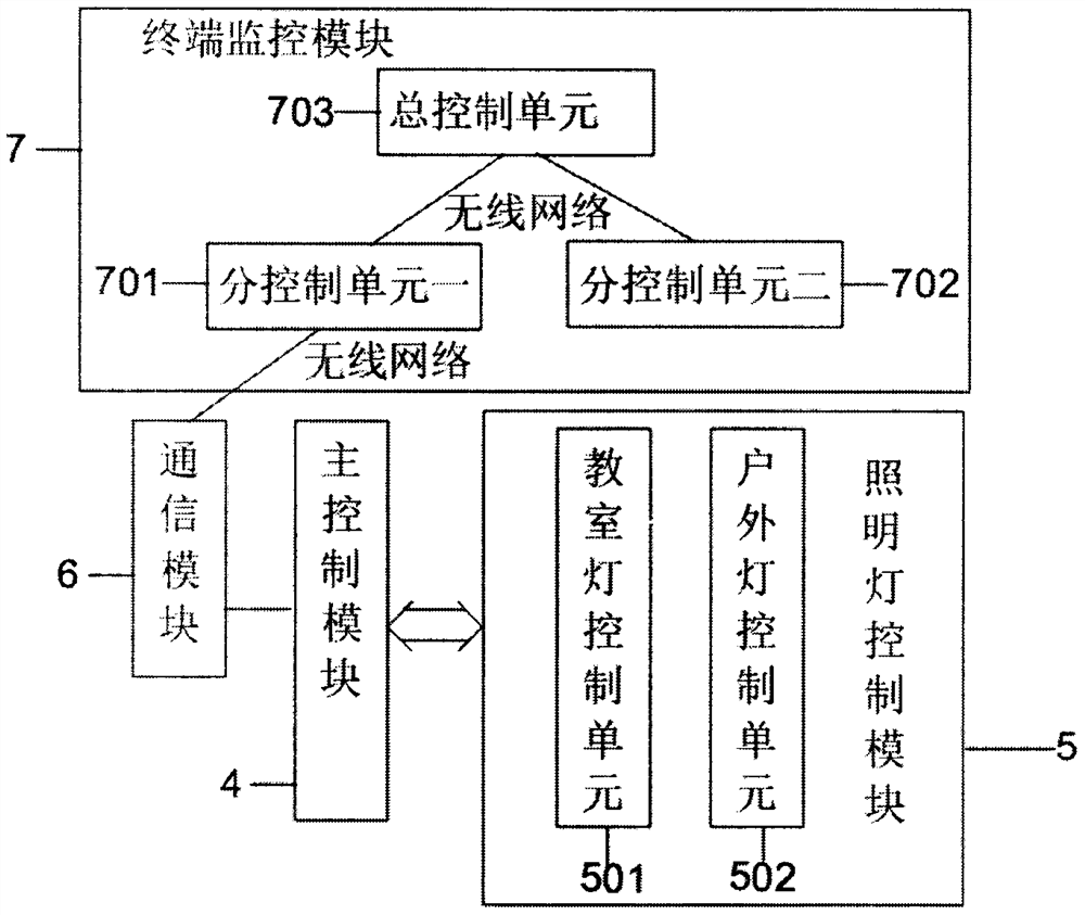
[0052] Embodiment 3: On the basis of Embodiment 2, please refer to Figure 5 , in a specific embodiment of the campus intelligent lighting control system described in the present invention, the network configuration method of the sub-control unit one 701, the specific steps are as follows:

[0053] S1: start;

[0054] S2: Initialize the sub-control unit; initialize each function module after the sub-control unit is started;

[0055] S3: Establish a network; build a specific network in the area;

[0056] S4: display the network ID; display the ID signal of a specific network;

[0057] S5: Enter the network monitoring state; search whether there is an authorized network nearby to connect and monitor the network connection state;

[0058] S6: Monitor whether there are nodes applying for the network, if there are nodes, enter S7, if not, enter S5;

[0059] S7: Assign network numbers to nodes and display them; assign network numbers to successfully connected smart mobile termin...


PUM


Abstract

The invention discloses a campus intelligent lighting control system, which relates to the technical field of intelligent lighting and comprises an external environment detection module, a camera monitoring module, a local control module, a main control module, a lighting lamp control module, a communication module, a terminal monitoring module and a peripheral control module. The external environment detection module and the camera monitoring module are used for detecting illumination, infrared rays and image data, the local control module is used for selecting a control mode, the main control module is used for receiving, processing and outputting the data, the communication module is used for realizing communication with a monitoring center, and the terminal monitoring module is used for monitoring a campus illumination system. According to the campus intelligent illumination control system, the illumination lamps are intelligently controlled to work by detecting the external illuminance condition and whether someone is around the illumination lamps, and the illumination lamps in different areas are intelligently monitored by the sub-control centers in the corresponding areas and can be in authorized connection with the networks in the corresponding areas through related APPs at the same time; and more differentiated control is realized.

Description

technical field [0001] The invention relates to the technical field of intelligent lighting, in particular to a campus intelligent lighting control system. Background technique [0002] With the progress of society, people continue to pay attention to education. Education is a basic national policy of our country. The whole society has invested great attention and huge manpower and material resources on education. The number of schools is also increasing. At the same time, the field of lighting As the most energy-consuming area in campus daily life, it is necessary to adopt an effective lighting control system. However, most of the current campus lighting control systems use various sensors to detect within a range, and then realize intelligent control of campus lighting. However, this This kind of lighting controlled by sensors easily conflicts with people's control intentions indoors, resulting in users not being able to get good lighting effects, and the campus lighting c...

Claims


Application Information

Patent Timeline
Patent Type & Authority Applications(China)
IPC IPC(8): H05B47/10H05B47/11H05B47/115H05B47/125H05B47/19
CPCH05B47/10H05B47/11H05B47/115H05B47/125H05B47/19Y02B20/40
Inventor 幸敏龙祖连
Owner 幸敏
Features
  • R&D
  • Intellectual Property
  • Life Sciences
  • Materials
  • Tech Scout
  • Unparalleled Data Quality
  • Higher Quality Content
  • 60% Fewer Hallucinations
Learn More