Thermosetting plastic shell forming equipment for manufacturing small car equipment

A technology for plastic shells and molding equipment, applied in applications, household components, household appliances, etc., can solve problems such as affecting the quality of finished products, easy scalding, and hardening of thermosetting plastic liquids, saving manpower and reducing costs.

Inactive Publication Date: 2022-03-29
ZHEJIANG IND POLYTECHNIC COLLEGE
View PDF0 Cites 0 Cited by
  • Summary
  • Abstract
  • Description
  • Claims
  • Application Information

AI Technical Summary

Problems solved by technology

[0004] In order to overcome the disadvantages that the thermosetting plastic liquid may harden during the production of the existing thermosetting plastic shell, thereby affecting the quality of the finished product, and at the same time, the temperature of the thermosetting plastic is relatively high during processing, and manual handling is easy to burn. The technical problem of the present invention : Provide a thermosetting plastic shell molding equipment for small car equipment manufacturing without handling, high degree of automation, and less manual operation

Method used


Image

  • Thermosetting plastic shell forming equipment for manufacturing small car equipment
  • Thermosetting plastic shell forming equipment for manufacturing small car equipment
  • Thermosetting plastic shell forming equipment for manufacturing small car equipment

Examples


Embodiment 1

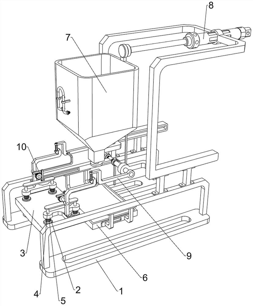
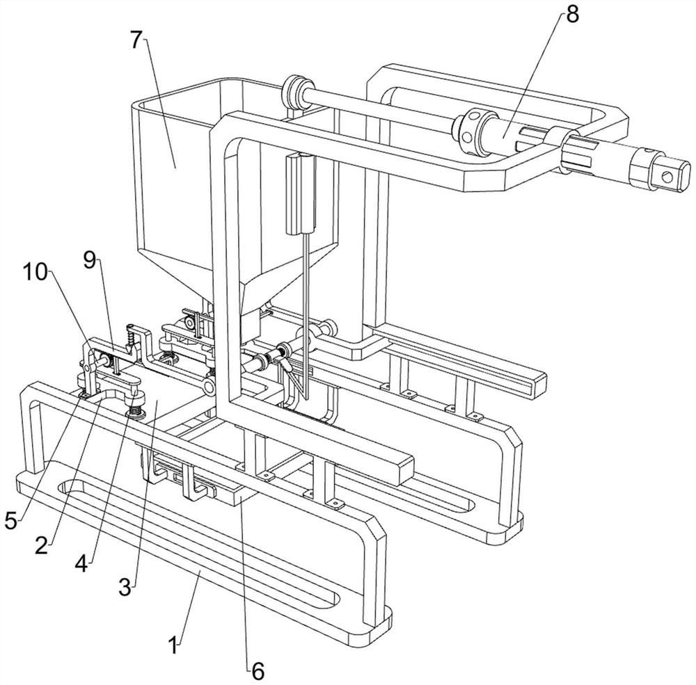
[0026] A thermosetting plastic shell molding equipment for small car equipment manufacturing, such as figure 1 , figure 2 , image 3 , Figure 4 , Figure 5 , Figure 6 and Figure 7 As shown, it includes a first support frame 1, a fixed plate 2, a lifting plate 3, a first connecting rod 4, a first spring 5, a fixed frame 6, a blanking mechanism 7, a power mechanism 8 and a pushing mechanism 9, and the first support The number of frames 1 is two, and the first support frame 1 is symmetrically placed front and back. The bottom of the first support frame 1 is provided with a non-slip pad, which can play a good anti-skid effect. The sides are slidingly equipped with fixed plates 2, and the first connecting rods 4 are slidingly arranged on the two fixed plates 2, and a lifting plate 3 is arranged between the bottoms of the two first connecting rods 4, and the first connecting rods 4 and the fixed Four first springs 5 ​​are connected between the bottoms of the plates 2, and ...

Embodiment 2

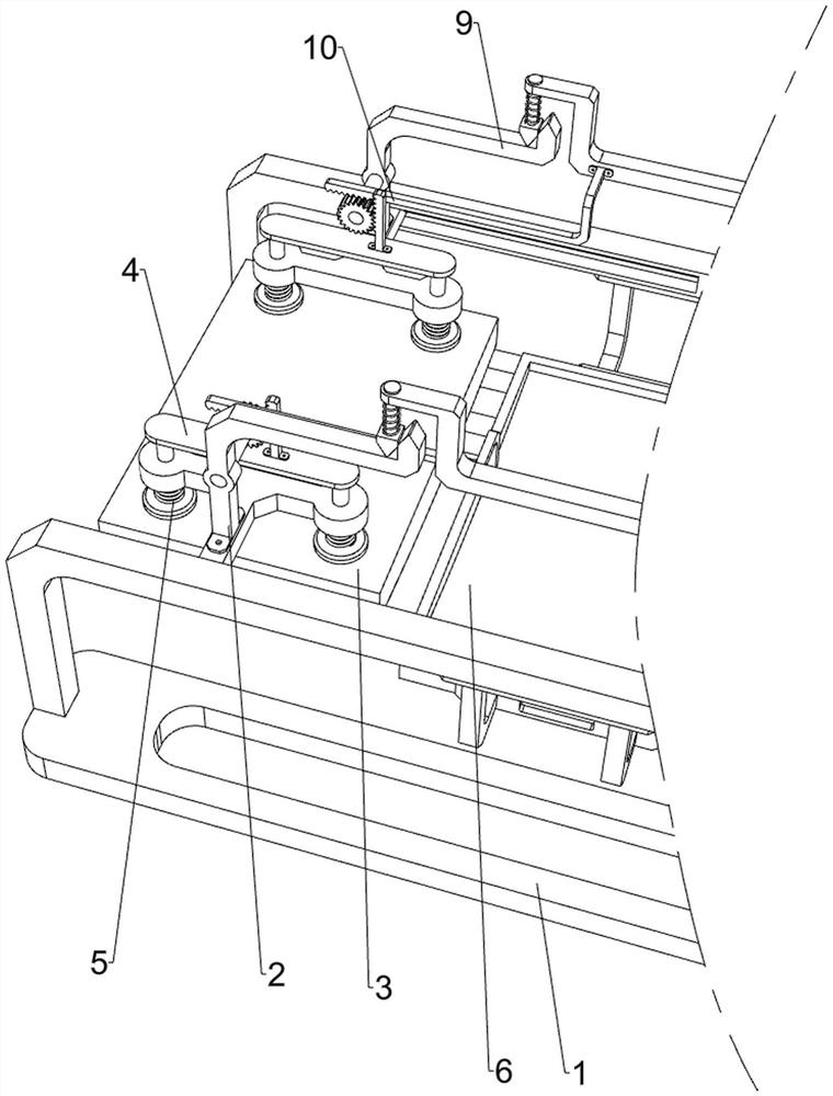
[0032] On the basis of Example 1, such as figure 1 , figure 2 and Figure 8 As shown, it also includes a pressing mechanism 10, and the pressing mechanism 10 includes a third connecting rod 101, a gear 102, a first rack 103 and a second rack 104, and the sides of the two wedge bars 90 are welded away from each other. There is a third connecting rod 101, a side of the two third connecting rods 101 away from each other is equipped with a gear 102, a side of the two second connecting rods 91 close to each other is welded with a second rack 104, the two first A first rack 103 is welded to the top of the connecting rod 4 , and both the first rack 103 and the second rack 104 are in meshing relationship with the gear 102 .

[0033] When the thermosetting plastic shell is processed and formed, it is still necessary to manually press the lifting plate 3 to extrude the thermosetting plastic, which is inconvenient. When the lifting plate 3 is located above the fixed frame 6, the teles...


PUM


Abstract

The invention relates to thermosetting plastic shell forming equipment, in particular to thermosetting plastic shell forming equipment for manufacturing small car equipment. The thermosetting plastic shell forming equipment for small car equipment manufacturing is free of carrying, high in automation degree and less in manual operation. Thermosetting plastic shell forming equipment for small car equipment manufacturing comprises two first supporting frames, fixing plates, a lifting plate and first connecting rods, the first supporting frames are symmetrically arranged front and back, and the fixing plates are slidably installed on the sides, close to each other, of the two first supporting frames; the two fixing plates are each provided with a first connecting rod in a sliding mode, and a lifting plate is arranged between the bottoms of the two first connecting rods. Thermosetting plastic can be melted into liquid through the heating pipe, so that a worker can conveniently process the thermosetting plastic into different shell shapes, and the processing operation of the worker is facilitated.

Description

technical field [0001] The invention relates to a thermosetting plastic shell forming device, in particular to a thermosetting plastic shell forming device for small car equipment manufacturing. Background technique [0002] With the development of the 21st century, the development of industrial technology has been improved day by day, especially the development of automobile level is also rapidly progressing, and the improvement of people's living standards, the material demand is also constantly increasing, in the automobile manufacturing industry , the demand for small cars continues to increase. As people's daily necessities, small cars have entered tens of millions of families. Small cars are mainly light, so some body shells are made of thermosetting plastics. When the existing thermosetting plastic shells are made, It is necessary to melt the thermosetting plastic first, and then transport the melted thermosetting plastic liquid to a specific mold. In this way, during...

Claims


Application Information

Patent Timeline
IPC IPC(8): B29C43/02B29C43/32B29C43/52B29C43/34B29L31/30
CPCB29C43/02B29C43/32B29C43/52B29C43/34B29L2031/3055B29C2043/3427
Inventor 黄芳
Owner ZHEJIANG IND POLYTECHNIC COLLEGE
Why Eureka
Try Eureka