
Improved structure of axial-flow type high-temperature smoke exhaust fan

A smoke exhaust fan, axial flow technology, applied to the components, heating methods, ventilation systems, etc. of the pumping device for elastic fluids, can solve the problems of high temperature and vulnerability of the fan, achieve stable water flow temperature, and avoid smoke Air overheating damages equipment and reduces difficulty

Active Publication Date: 2022-03-29
靖江市易凯通风设备有限公司
View PDF6 Cites 0 Cited by
  • Summary
  • Abstract
  • Description
  • Claims
  • Application Information

AI Technical Summary

Problems solved by technology

[0004] The purpose of the present invention is to solve the problem of high-temperature and fragile fans in the prior art, and propose an improved structure of an axial-flow high-temperature exhaust fan

Method used


Image

  • Improved structure of axial-flow type high-temperature smoke exhaust fan
  • Improved structure of axial-flow type high-temperature smoke exhaust fan
  • Improved structure of axial-flow type high-temperature smoke exhaust fan

Examples


Embodiment

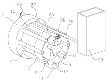
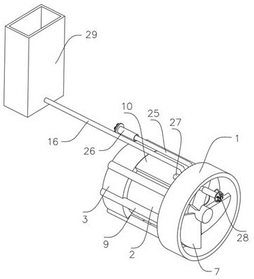
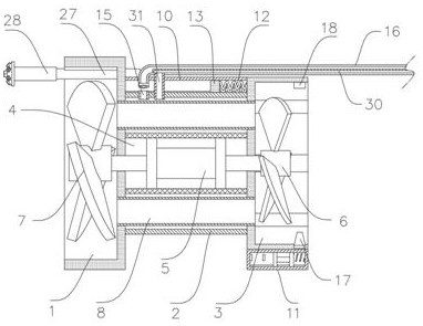
[0027] refer to Figure 1-7 , an improved structure of an axial-flow high-temperature smoke exhaust fan, including a front box 1, a pipe sleeve 2 fixed to the side wall of the front box 1, a rear box 3 fixed to the end of the pipe sleeve 2, the front box 1 and the rear box 3 The side walls of the machine cover 4 are fixed together, the inner wall of the machine cover 4 is fixed with a motor 5, the motor 5 is a double-headed motor, and the two output shafts of the motor 5 are respectively fixed with a rear blade 6 and a front blade 7, and the rear blade 6 and front fan blades 7 are respectively located in the rear box 3 and the front box 1, the output shaft of the motor 5 is sealed and penetrates through the rotation connection with the front box 1 and the rear box 3 to avoid water leakage, and the side wall of the front box 1 is inserted through and connected with the rear box. A plurality of inner through pipes 8 and outer through pipes 9 connected inside the box 3, the inner...


PUM


Abstract

The improved structure comprises a front box, a pipe sleeve is fixed to the side wall of the front box, a rear box is fixed to the end of the pipe sleeve, a machine sleeve is fixed to the side wall of the front box and the side wall of the rear box together, a motor is fixed to the inner wall of the machine sleeve, the motor is a double-end motor, and the two ends of the machine sleeve are connected with the two ends of the machine sleeve. A rear fan blade and a front fan blade are fixed to two output shafts of the motor respectively and located in the rear box and the front box respectively, a plurality of inner through pipes and outer through pipes which are communicated with the interior of the rear box are inserted into the side wall of the front box in a penetrating mode, and the inner through pipes are located in the pipe sleeve. The device has the advantages that the temperature is controlled after the air flow is exhausted, direct pollution to the environment is reduced, the smoke treatment difficulty of follow-up equipment is reduced, heat generated by the motor during operation can also be absorbed by water flow, the motor keeps the effective operation temperature, the motor does not make direct contact with the air flow, the damage speed of the motor is greatly reduced, and the service life of the motor is prolonged. And the service life of the motor is greatly prolonged.

Description

technical field [0001] The invention relates to the technical field of fans, in particular to an improved structure of an axial-flow high-temperature exhaust fan. Background technique [0002] Axial flow fan is also called local fan. It is different from ordinary fans. Its motor and fan blades are in a cylinder. The shape is a cylinder. It is used for local ventilation. , you can connect the air tube to send the wind to the designated area. [0003] After the existing axial flow fan is installed, it is usually used to discharge high-temperature flue gas, especially in the field of fire protection. Because the driving parts of the existing fan are in direct contact with the air flow, the high-temperature flue gas can easily cause direct impact on the driving parts Damage, which greatly reduces the service life of the driving components, and is extremely easy to damage, which leads to inconvenience in the use of equipment, and the existing equipment cannot restrain the emissi...

Claims


Application Information

Patent Timeline
Patent Type & Authority Applications(China)
IPC IPC(8): F04D25/08F04D29/58F24F7/007
CPCF04D25/08F04D25/082F04D29/5806F04D29/5846F24F7/007
Inventor 陈兴
Owner 靖江市易凯通风设备有限公司
Learn More