
Simulation method and simulation system of permanent magnet synchronous generator based on digital Koelreuteria

A technology of permanent magnet synchronization and simulation method, which is applied in the field of simulation system, can solve the problems that the generator equipment cannot be modeled carefully, the calculation speed is slow, and the digital twin cannot be satisfied, so as to achieve the effect of improving computing efficiency and real-time performance

Pending Publication Date: 2022-03-29
INNER MONGOLIA UNIV OF TECH
View PDF0 Cites 0 Cited by
  • Summary
  • Abstract
  • Description
  • Claims
  • Application Information

AI Technical Summary

Problems solved by technology

However, the current modeling of wind power systems is mostly based on Matlab / Simulink mathematical models. Although this type of model has the advantages of simple structure and clear logic, it cannot do detailed modeling for the generator equipment in the system, making the virtual model of the equipment There are insufficient idealization and standardization, especially for complex electromechanical equipment such as generators, simple mathematical models cannot meet the needs of realizing digital twins
Although the finite element model for the equipment body can achieve the fine design and internal multi-physics analysis of the generator equipment, but because the wind power system generator equipment is affected by the wind turbine and the control system cannot be ignored, this kind of modeling method There are deficiencies in the consideration of system coupling, and the finite element model often slows down the calculation speed while ensuring the calculation accuracy, which is contrary to the real-time concept of the DT model
In addition, the conventional modeling platform does not have the ability to deploy the Internet of Things, so that the built virtual model cannot realize the data interaction and fusion analysis with the physical wind turbine in the later stage

Method used


Image

  • Simulation method and simulation system of permanent magnet synchronous generator based on digital Koelreuteria
  • Simulation method and simulation system of permanent magnet synchronous generator based on digital Koelreuteria
  • Simulation method and simulation system of permanent magnet synchronous generator based on digital Koelreuteria

Examples


Embodiment Construction

[0034] Reference will now be made in detail to the exemplary embodiments, examples of which are illustrated in the accompanying drawings. When the following description refers to the accompanying drawings, the same numerals in different drawings refer to the same or similar elements unless otherwise indicated. The implementations described in the following exemplary examples do not represent all implementations consistent with the present disclosure. Rather, they are merely examples of apparatuses and methods consistent with aspects of the present disclosure as recited in the appended claims.

[0035] The terminology used in the present disclosure is for the purpose of describing particular embodiments only, and is not intended to limit the present disclosure. As used in this disclosure and the appended claims, the singular forms "a", "the", and "the" are intended to include the plural forms as well, unless the context clearly dictates otherwise. It should also be understood...


PUM


Abstract

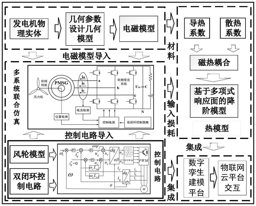
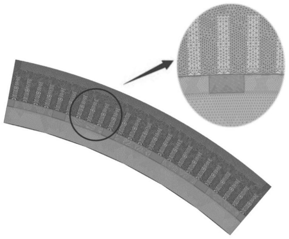
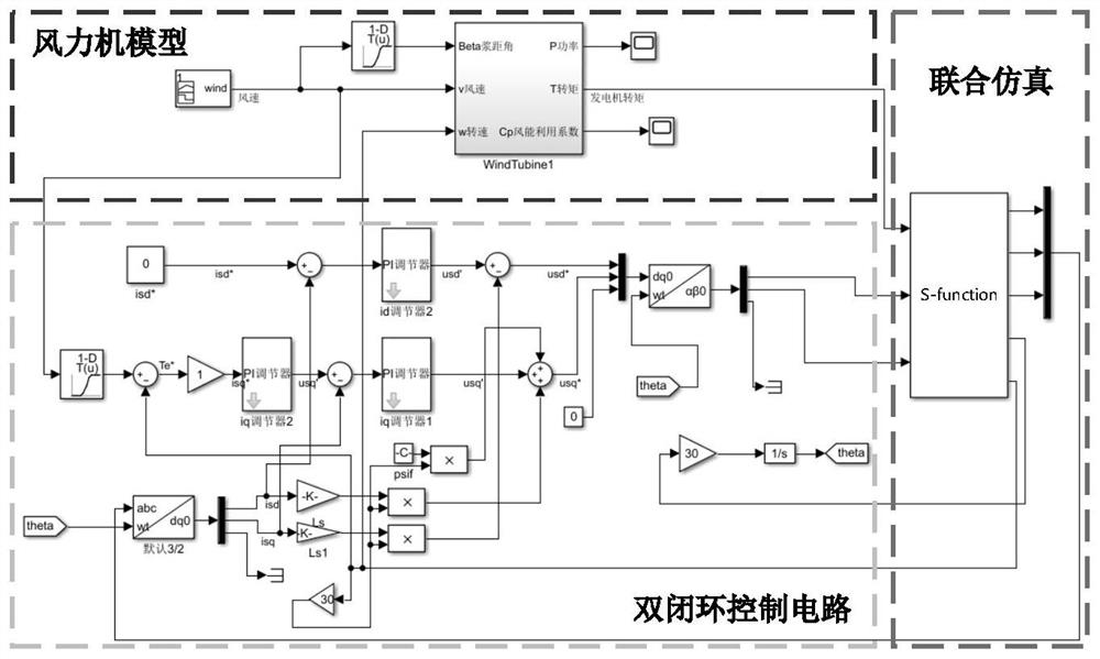
The invention provides a simulation method and a simulation system of a permanent magnet synchronous generator based on digital Koelreuteria. The simulation method comprises the following steps: adopting Maxwell 2D to construct an electromagnetic model for a 2MW permanent magnet synchronous generator; building an external circuit and a control circuit of the 2MW permanent magnet synchronous generator in the Simulink; and carrying out joint simulation to realize field-circuit coupling so as to establish a magnetic-thermal coupling model, and carrying out order reduction processing and integration on the magnetic-thermal coupling model to form a digital twin virtual model. According to the simulation method, the effectiveness of the modeling method and the real operation characteristics of the mapping entity model are improved.

Description

technical field [0001] The present invention relates to the field of modeling methods for permanent magnet synchronous generators (PMSG) in wind power systems, in particular to a simulation method and simulation system for permanent magnet synchronous generators based on digital twins. Background technique [0002] As a complex electromechanical device, wind turbines have received extensive attention in the field of power equipment condition monitoring and fault diagnosis since the digital twin technology (Digital Twin, DT) was proposed. With the continuous improvement and maturity of sensor, model simulation, Internet of Things and other related technologies, the application of DT to the condition monitoring and fault diagnosis of wind turbines has become a current research hotspot. [0003] At present, scholars at home and abroad have conducted research on the application of wind turbine DT technology in different components such as wind power transmission system gearboxes...

Claims


Application Information

Patent Timeline
IPC IPC(8): G06F30/23G06F30/17G06F30/28G06F113/06G06F113/08G06F119/14G06F119/08
CPCG06F30/23G06F30/17G06F30/28G06F2113/06G06F2113/08G06F2119/14G06F2119/08
Inventor 刘利强齐咏生尹彦博李永亭马然
Owner INNER MONGOLIA UNIV OF TECH
Learn More