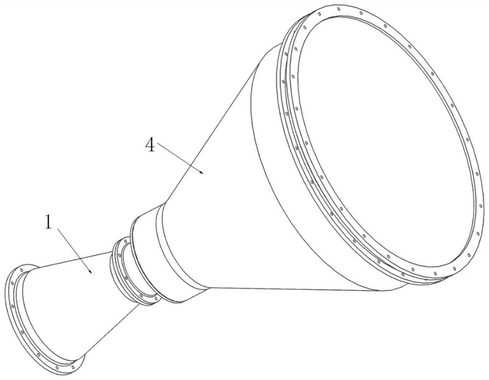
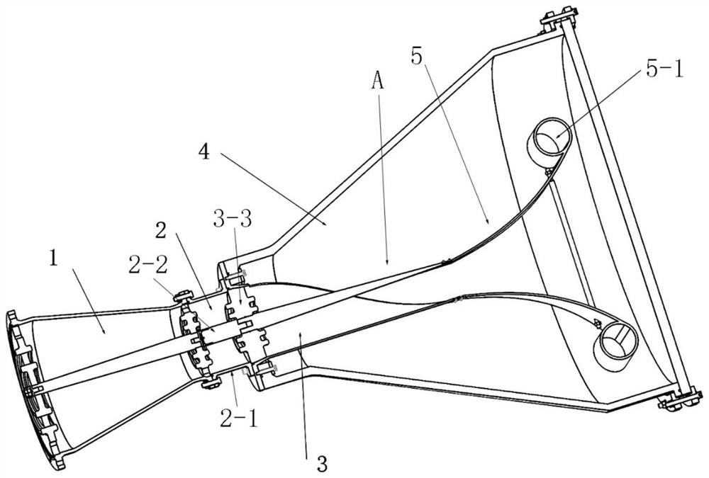
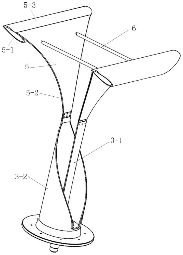
High-power ultra-wideband electromagnetic radiation antenna
An electromagnetic radiation and ultra-broadband technology, applied in the field of radiation antennas, can solve problems such as limited emission efficiency, damage to weapons, and antennas destroyed by ignition, and achieve the effects of improving emission gain, avoiding burning devices, and avoiding ignition
- Summary
- Abstract
- Description
- Claims
- Application Information
AI Technical Summary
Problems solved by technology
Method used
Image

Examples
Embodiment Construction
[0026] A detailed description will be given below of embodiments of the present invention. Although the present invention will be described and illustrated in conjunction with some specific embodiments, it should be noted that the present invention is not limited to these embodiments. On the contrary, any modification or equivalent replacement made to the present invention shall be included in the scope of the claims of the present invention.
[0027] In addition, in order to better illustrate the present invention, numerous specific details are given in the specific embodiments below. It will be understood by those skilled in the art that the present invention may be practiced without these specific details.
[0028] High-power ultra-wideband electromagnetic waves are an effective solution to deal with drones and high-speed missiles, but the core is the source and transmitting antenna that generate high-power ultra-wideband electromagnetic waves. The withstand voltage and b...
PUM
 Abstract
Description
Claims
Application Information