
Ceramic glaze spraying device with dust collecting function

A technology for dust collection and ceramics, which is applied to the field of ceramic glaze spraying devices with dust collection function, can solve the problems of deviation of spraying direction of atomized glaze slurry, influence on spraying effect, huge structure, etc. Post-processing, compact overall size effect

Pending Publication Date: 2022-04-01
HUNAN HUALIAN CHINA IND
View PDF13 Cites 0 Cited by
  • Summary
  • Abstract
  • Description
  • Claims
  • Application Information

AI Technical Summary

Problems solved by technology

[0002] At present, in the process of spraying glaze on ceramics, if it is necessary to avoid air pollution, it is generally placed in a closed space for spraying glaze, and the direction of spraying glaze is blocked and intercepted by a baffle, or the redundant air is sucked by negative pressure. The atomized glaze slurry and dust are absorbed to avoid the atomized glaze slurry or dust flying randomly affecting the working environment, but the use of these two methods will affect the original direction of the atomized glaze slurry sprayed by the nozzle, resulting in the spraying of the atomized glaze slurry The deviation of the direction will affect the effect of spraying glaze. At the same time, placing the spraying work in a closed space often has a huge structure and takes up a lot of space.

Method used


Image

  • Ceramic glaze spraying device with dust collecting function
  • Ceramic glaze spraying device with dust collecting function
  • Ceramic glaze spraying device with dust collecting function

Examples


Embodiment Construction

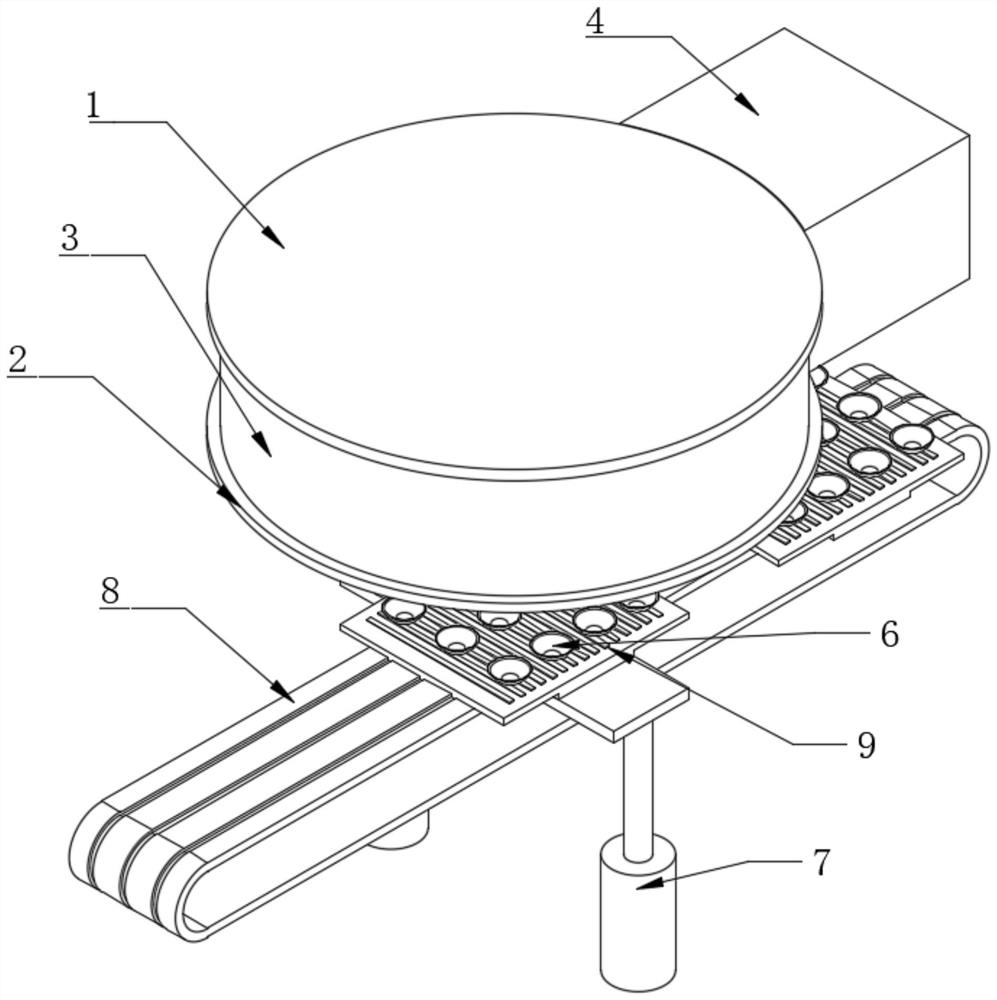
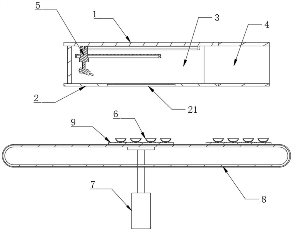
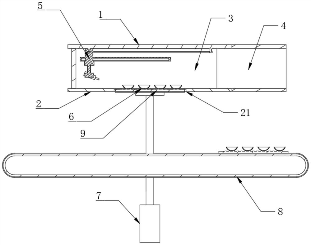
[0022] like Figure 1-6 As shown, the present invention includes an upper baffle 1, a lower baffle 2, and an annular side plate 3 rotatably arranged between the upper baffle 1 and the lower baffle 2, and also includes a power member for driving the annular side plate 3 to rotate. The annular side plate 3 is provided with an exhaust channel 4 extending outward, the upper partition 1 is provided with a glaze spray assembly 5, and the lower partition 2 is provided with an installation port 21 for installing ceramics 6, and the glaze spray assembly 5 includes a nozzle 51 and the annular driving member that drives the spray head 51 to rotate around the installation port 21, the exhaust passage 4 always corresponds to the direction of the spray head 51.

[0023] In the present invention, an annular side plate 3 is arranged between the upper partition plate 1 and the lower partition plate 2, and an exhaust channel 4 corresponding to the direction of the glaze spraying nozzle 51 is ex...


PUM


Abstract

The invention belongs to the field of ceramic glaze spraying, and particularly relates to a ceramic glaze spraying device with a dust collection function, which comprises an upper partition plate, a lower partition plate and an annular side plate rotationally arranged between the upper partition plate and the lower partition plate, and further comprises a power part for driving the annular side plate to rotate, the upper partition plate is provided with a glaze spraying assembly, the lower partition plate is provided with a mounting opening used for mounting ceramics, the glaze spraying assembly comprises a spray head and an annular driving part used for driving the spray head to rotate around the mounting opening, and the exhaust channel always corresponds to the spray head in direction. The exhaust channel corresponding to the direction of the glaze spraying nozzle is arranged on the annular side plate in an extending mode, dust collection treatment in the glaze spraying process is achieved, the exhaust channel always corresponds to the direction of the nozzle, it is guaranteed that the flow direction of sprayed atomized glaze slip in the glaze spraying process is accurate, and glaze spraying is more uniform.

Description

technical field [0001] The invention belongs to the field of ceramic glaze spraying, and in particular relates to a ceramic glaze spraying device with dust collecting function. Background technique [0002] At present, in the process of spraying glaze on ceramics, if it is necessary to avoid air pollution, it is generally placed in a closed space for spraying glaze, and the direction of spraying glaze is blocked and intercepted by a baffle, or the redundant air is sucked by negative pressure. The atomized glaze slurry and dust are absorbed to avoid the atomized glaze slurry or dust flying randomly affecting the working environment, but the use of these two methods will affect the original direction of the atomized glaze slurry sprayed by the nozzle, resulting in the spraying of the atomized glaze slurry Deviations in the direction will affect the effect of spraying glaze. At the same time, placing the spraying work in a closed space often has a huge structure and occupies a ...

Claims


Application Information

Patent Timeline
Patent Type & Authority Applications(China)
IPC IPC(8): B28B11/04B28B17/04
CPCY02P70/10
Inventor 曾淼汪大谷
Owner HUNAN HUALIAN CHINA IND
Learn More