Detachable positioning device on logistics supply chain

A positioning device and on-chain technology, which is applied in the direction of unloading device, conveyor objects, transportation and packaging, etc., can solve the adverse effects of disassembling the positioning device, the positioning device does not have waterproof function, and the crystal is easily melted by heat and flows into the positioning device and other issues to achieve the effect of preventing adverse effects

Pending Publication Date: 2022-04-01
广东鑫港湾供应链管理有限公司
View PDF1 Cites 1 Cited by
  • Summary
  • Abstract
  • Description
  • Claims
  • Application Information

AI Technical Summary

Problems solved by technology

[0004] However, the technical solution provided by this patent does not have a waterproof function for the positioning device. When transporting cold chain items in a high-temperature environment in

Method used


Image

  • Detachable positioning device on logistics supply chain
  • Detachable positioning device on logistics supply chain
  • Detachable positioning device on logistics supply chain

Examples


Example Embodiment

[0044] Example 1

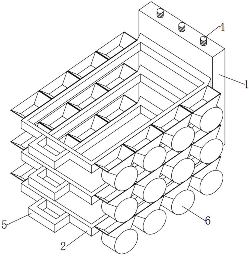
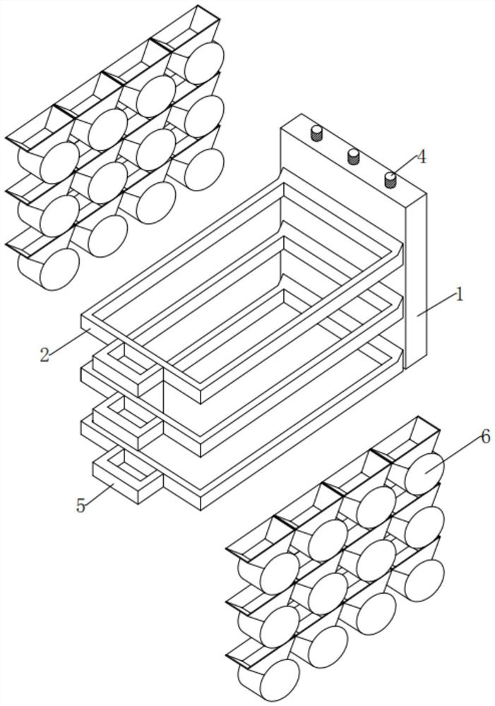
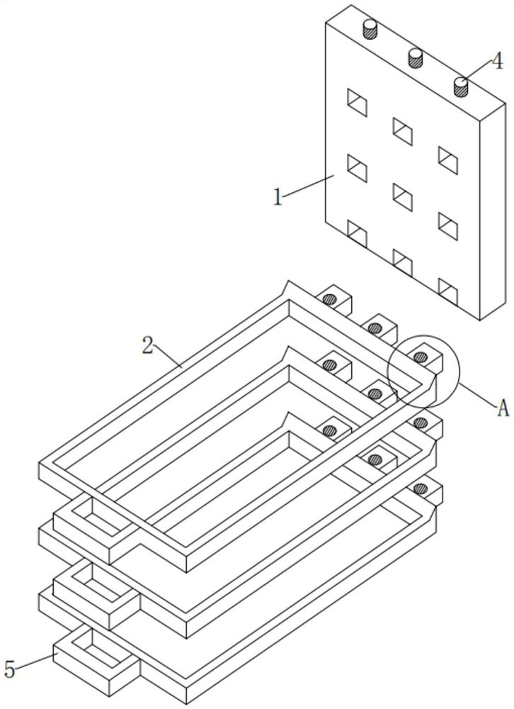
[0045] see Figure 1-5 , in an embodiment of the present invention, a detachable positioning device on a logistics supply chain, comprising:

[0046] Support plate 1, the appearance of the support plate 1 is a flat rectangular parallelepiped shape up and down vertical direction, the inner position of the support plate 1 is equidistantly arranged with a number of square grooves penetrating left and right, and the inner position of the support plate 1 is also equidistantly arranged. There are several circular grooves running through up and down, the inner wall of the circular groove is provided with an internal thread, the circular groove passes through the center of the bottom end of the square groove, and a screw 4 is installed in the circular groove in an up-down and vertical direction;

[0047] The support plate 1 here is for the purpose of providing fixed support for each positioning frame 2, and the square groove opened on it is for docking with the plu...

Example Embodiment

[0063] Example 2

[0064] see Figure 5 , Figure 7-8 , compared with Embodiment 1, the difference between the embodiment of the present invention is that the two ends of the top and bottom of the diversion bucket 7 are respectively provided with a large inlet and a small outlet, and the left and right plates of the diversion bucket 7 are outside the rear side. The surface is fixedly installed on the front outer surface of the positioning frame 2, and the front outer surfaces of the left plate and the right plate of the diversion bucket 7 are fixedly installed on the rear outer surface of the front plate of the diversion bucket 7. The plate and the right plate are respectively inclined in the shape of left high and right low and right high and left low. length;

[0065] The large inlet opened at the top of the guide bucket 7 here is to facilitate the flow of water from the front and rear sides of the top of the positioning frame 2, and the small outlet opened at the bottom ...

Example Embodiment

[0075] Example 3

[0076] see Figure 5-8 , the difference between the embodiment of the present invention and the embodiment 1 is that the water absorbing component 12 includes:

[0077] The partition plate 13, the upper left end of the water collecting tank 8 is fixedly installed with the partition plate 13 in the front and rear horizontal directions. The outer surface is fixedly installed at the upper left end position of the front and rear inner walls of the water collecting tank 8. The outer surface of the bottom end of the right side of the partition plate 13 is normally attached to the outer surface of the left side of the guide plate 11, and the bottom end of the left side of the partition plate 13 is outside. There is a distance between the surface and the middle end surface of the left inner wall of the sump 8 and the distance is greater than the interval between the right outer surface of the guide plate 11 and the middle end surface of the right inner wall of the ...


PUM


Abstract

The invention provides a detachable positioning device on a logistics supply chain. The detachable positioning device comprises a supporting plate, and a plurality of positioning frames are movably installed on the outer surface of the left side of the supporting plate in an equally adjacent mode; the waterproof assemblies capable of preventing water from flowing into the square groove are fixedly installed on the outer surfaces of the front side and the rear side of the positioning frame in an equally adjacent mode, and each waterproof assembly comprises a flow guiding hopper, a water collecting groove, a water guiding assembly capable of guiding the water to flow in and collect the water and a water absorbing assembly capable of absorbing the flowing-in water. According to the detachable positioning device on the logistics supply chain, articles can be positioned and transported, dismounting is convenient, meanwhile, the positioning device has a waterproof function, even if cold-chain articles are transported in a high-temperature environment in summer, crystals outside the articles are heated and melted, water is not prone to flowing into the positioning device, and the positioning device is convenient to use. The moisture can be collected and treated in time, and adverse effects on later disassembly of the positioning device are prevented.

Description

technical field [0001] The invention relates to the technical field of logistics supply chain, and more specifically, relates to a detachable positioning device on the logistics supply chain. Background technique [0002] When the existing logistics supply chain conveyor belt is in use, the surface of the conveyor belt is generally not provided with a positioning structure, so that the items are prone to skewing and falling during transportation. [0003] In view of the above-mentioned problems, regarding the technical problem that it is inconvenient to locate items on the surface of the conveyor belt, which makes it easy to drop during transportation, etc., after a large number of searches, we found a detachable positioning device on the logistics supply chain with the patent number CN202020896513.6 , including the main body of the conveyor belt, the top surface of the main body of the conveyor belt is fixedly connected with the installation seat, and the surface of the ins...

Claims


Application Information

Patent Timeline
IPC IPC(8): B65G47/24B65D81/26B65D25/52F26B5/12F26B5/16F26B25/00
Inventor 袁美雄郭灵芝肖青兰
Owner 广东鑫港湾供应链管理有限公司
Why Eureka
Try Eureka