
Water grate for drainage ditch

A technology of drainage ditch and water grate, which is applied to drainage structures, waterway systems, water supply devices, etc., can solve the problems of delayed cleaning, high labor intensity, slow cleaning speed, etc., so as to prevent road surface water and improve work efficiency. , to avoid the effect of being blocked

Inactive Publication Date: 2022-04-01
车扬
View PDF0 Cites 0 Cited by
  • Summary
  • Abstract
  • Description
  • Claims
  • Application Information

AI Technical Summary

Problems solved by technology

[0002] In the process of road construction, in order to prevent the road surface from causing a large amount of water accumulation in rainy and snowy weather and meet the urban ground drainage needs, a large number of underground drainage pipes and drainage ditches are usually installed. In order to prevent the drainage ditches from being blocked by solid debris, usually Add a cover plate with a drainage channel on the drainage ditch, that is, a water grate to block, but after a period of use, the slots on the gutter water grate will be blocked by fine debris such as dust, fibers, etc., resulting in drainage ditch The drainage capacity of the water grate is blocked, which affects the normal drainage effect
[0003] The existing cleaning methods are usually cleaned regularly by sanitation workers. The cleaning speed is slow, the efficiency is low, and the labor intensity is high. Especially the inside of the drainage hole is very difficult to clean effectively, and the cleaning time is delayed, resulting in the drainage system not being able to drain normally. And cause the road to accumulate water, affecting people's travel

Method used


Image

  • Water grate for drainage ditch
  • Water grate for drainage ditch
  • Water grate for drainage ditch

Examples


Embodiment Construction

[0018] The following will clearly and completely describe the technical solutions in the embodiments of the present invention with reference to the accompanying drawings in the embodiments of the present invention. Obviously, the described embodiments are only some of the embodiments of the present invention, not all of them. Based on the embodiments of the present invention, all other embodiments obtained by persons of ordinary skill in the art without making creative efforts belong to the protection scope of the present invention.

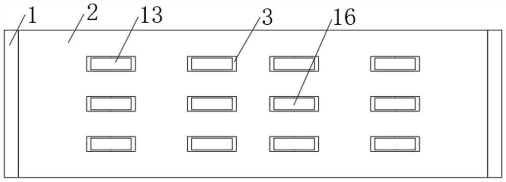
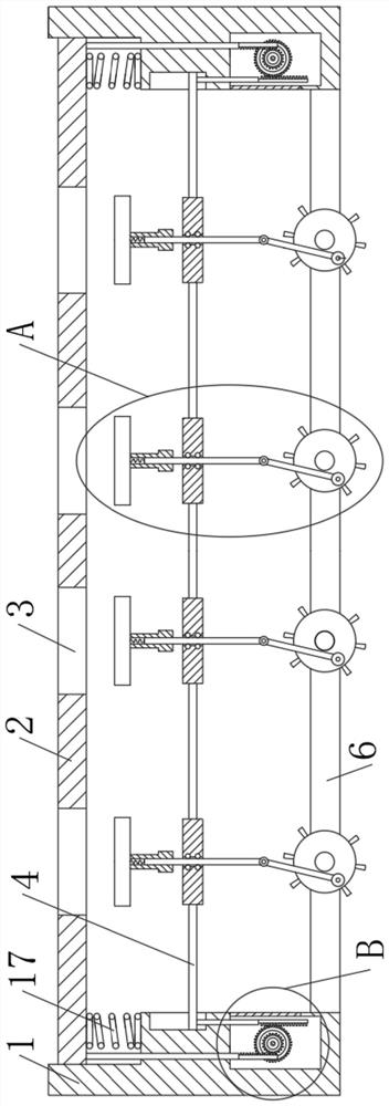
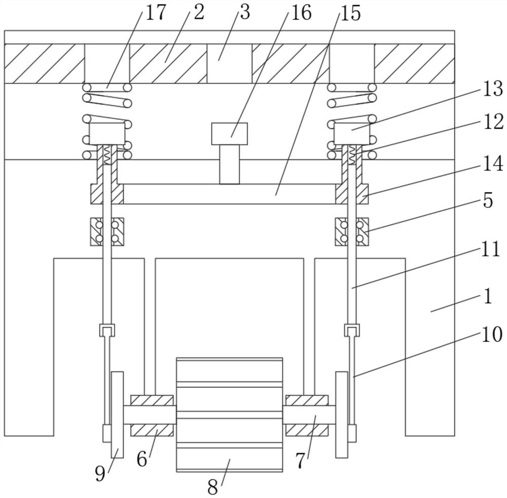
[0019] see Figure 1-Figure 4 , a water grate for drainage ditches, comprising two groups of bases 1, the middle parts of the two groups of bases 1 are movably sleeved with a cover plate 2, the front of the cover plate 2 is provided with several sets of equidistantly arranged water holes 3, and the two groups of bases 1 The movable rod 4 is socketed in the middle part of the opposite side, and the movable rod not only plays a role of supporting a...


PUM


Abstract

The invention relates to the technical field of road auxiliary equipment, and discloses a water grate for a drainage ditch, which comprises two groups of bases, the middle parts of the two groups of bases are movably sleeved with a cover plate, the front surface of the cover plate is provided with a plurality of groups of water passing holes arranged at equal intervals, and the middle parts of the opposite sides of the two groups of bases are movably sleeved with movable rods. Through the arrangement of a first gear, a fluted disc and a movable rod, when a pedestrian steps on the cover plate, the cover plate moves downwards by a small distance, the displacement of a second straight rod can be amplified through the cooperation of the first gear and the fluted disc, the second straight rod can push the movable rod to generate large displacement upwards, and a movable ejection block and a fixed ejection block are introduced into a water passing hole as well; impurities and dirt accumulated and blocked in the water passing hole are loosened and discharged, the interior of the water passing hole is further kept clean, and the situation that the interior of the water passing hole can be cleaned through treading of pedestrians when a water wheel cannot be driven to rotate due to water shortage in the drainage ditch can be avoided.

Description

technical field [0001] The invention relates to the technical field of road auxiliary equipment, in particular to a water grate for drainage ditches. Background technique [0002] In the process of road construction, in order to prevent the road surface from causing a large amount of water accumulation in rainy and snowy weather and meet the urban ground drainage needs, a large number of underground drainage pipes and drainage ditches are usually installed. In order to prevent the drainage ditches from being blocked by solid debris, usually Add a cover plate with a drainage channel on the drainage ditch, that is, a water grate to block, but after a period of use, the slots on the gutter water grate will be blocked by fine debris such as dust, fibers, etc., resulting in drainage ditch The drainage capacity of the water grate is hindered, which affects the normal drainage effect. [0003] The existing cleaning methods are usually cleaned regularly by sanitation workers. The c...

Claims


Application Information

Patent Timeline
Patent Type & Authority Applications(China)
IPC IPC(8): E03F5/06E03F7/00
Inventor 车扬
Owner 车扬
Learn More